USA/GLOBAL: +1-949-461-9292
EUROPE: +39-011-3052-794
CONTACT US

Category: Profilometry | Flatness and Warpage


Roughness Mapping Inspection using 3D Profilometry

ROUGHNESS MAPPING INSPECTION

USING 3D PROFILOMETRY

Prepared by

DUANJIE, PhD

INTRODUCTION

Surface roughness and texture are critical factors that impact the final quality and performance of a product. A thorough understanding of surface roughness, texture, and consistency is essential for selecting the best processing and control measures. Fast, quantifiable, and reliable inline inspection of product surfaces is in need to identify the defective products in time and optimize production line conditions.

IMPORTANCE OF 3D NON-CONTACT PROFILOMETER FOR IN-LINE SURFACE INSPECTION

Surface defects in products result from materials processing and product manufacturing. Inline surface quality inspection ensures the tightest quality control of the end products. NANOVEA 3D Non-Contact Optical Profilers utilize Chromatic Light technology with unique capability to determine the roughness of a sample without contact. The line sensor enables scanning of the 3D profile of a large surface at a high speed. The roughness threshold, calculated in real-time by the analysis software, serves as a fast and reliable pass/fail tool.

MEASUREMENT OBJECTIVE

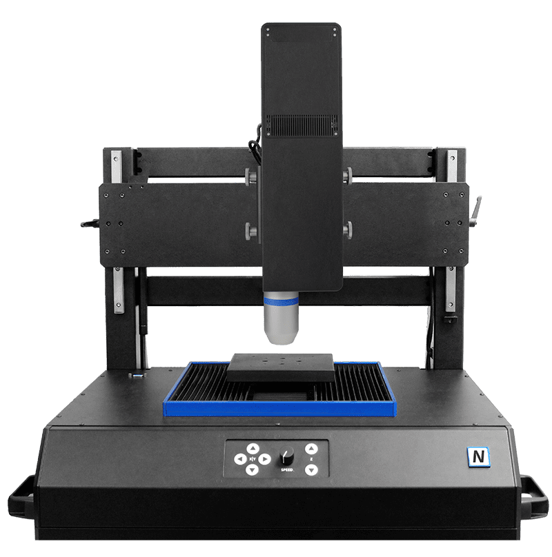
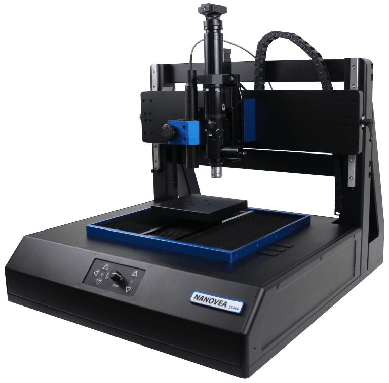
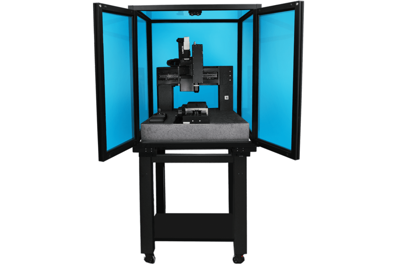
In this study, the NANOVEA ST400 equipped with a high-speed sensor is used to inspect the surface of a Teflon sample with defect to showcase the capability of NANOVEA

Non-Contact Profilometers in providing fast and reliable surface inspection in a production line.

NANOVEA

ST400

RESULTS & DISCUSSION

3D Surface Analysis of the Roughness Standard Sample

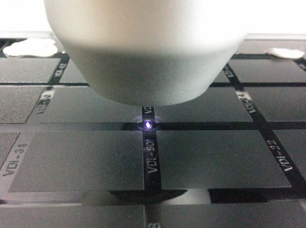
The surface of a Roughness Standard was scanned using a NANOVEA ST400 equipped with a high-speed sensor that generates a bright line of 192 points, as shown in FIGURE 1. These 192 points scan the sample surface at the same time, leading to significantly increased scan speed.

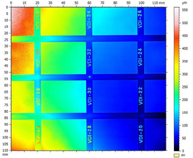
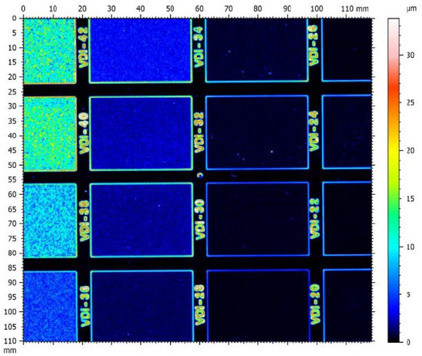
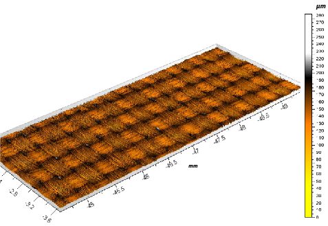
FIGURE 2 shows false color views of the Surface Height Map and Roughness Distribution Map of the Roughness Standard Sample. In FIGURE 2a, the Roughness Standard exhibits a slightly slanted surface as represented by the varied color gradient in each of the standard roughness blocks. In FIGURE 2b, homogeneous roughness distribution is shown in different roughness blocks, the color of which represents the roughness in the blocks.

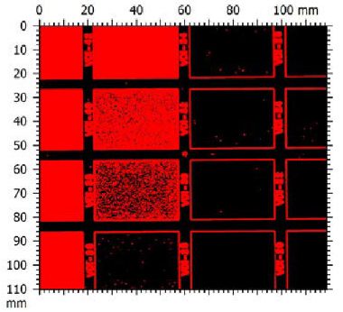
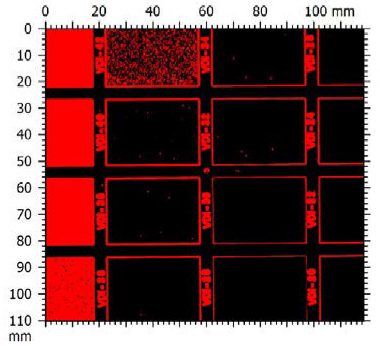
FIGURE 3 shows the examples of the Pass/Fail Maps generated by the Analysis Software based on different Roughness Thresholds. The roughness blocks are highlighted in red when their surface roughness is above a certain set threshold value. This provides a tool for the user to set up a roughness threshold to determine the quality of a sample surface finish.

FIGURE 1: Optical line sensor scanning on the Roughness Standard sample

a. Surface Height Map:

b. Roughness Map:

FIGURE 2: False color views of the Surface Height Map and Roughness Distribution Map of the Roughness Standard Sample.

FIGURE 3: Pass/Fail Map based on the Roughness Threshold.

Surface Inspection of a Teflon Sample with Defects

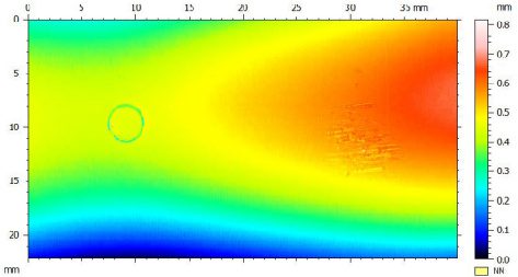
Surface Height Map, Roughness Distribution Map and Pass/Fail Roughness Threshold Map of the Teflon sample surface are shown in FIGURE 4. The Teflon Sample has a ridge form at the right center of the sample as shown in the Surface Height Map.

a. Surface Height Map:

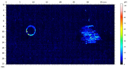
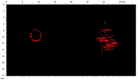
The different colors in the pallet of FIGURE 4b represents the roughness value on the local surface. The Roughness Map exhibits a homogeneous roughness in the intact area of the Teflon sample. However, the defects, in the forms of an indented ring and a wear scar are highlighted in bright color. The user can easily set up a Pass/Fail roughness threshold to locate the surface defects as shown in FIGURE 4c. Such a tool allows users to monitor in situ the product surface quality in the production line and discover defective products in time. The real-time roughness value is calculated and recorded as the products pass by the in-line optical sensor, which can serve as a fast but reliable tool for quality control.

b. Roughness Map:

c. Pass/Fail Roughness Threshold Map:

FIGURE 4: Surface Height Map, Roughness Distribution Map and Pass/Fail Roughness Threshold Map of the Teflon sample surface.

CONCLUSION

In this application, we have shown how the NANOVEA ST400 3D Non-Contact Optical Profiler equipped with an optical line sensor works as a reliable quality control tool in an effective and efficient manner.

The optical line sensor generates a bright line of 192 points that scan the sample surface at the same time, leading to significantly increased scan speed. It can be installed in the production line to monitor the surface roughness of the products in situ. The roughness threshold works as a dependable criteria to determine the surface quality of the products, allowing users to notice the defective products in time.

The data shown here represents only a portion of the calculations available in the analysis software. NANOVEA Profilometers measure virtually any surface in fields including Semiconductor, Microelectronics, Solar, Fiber Optics, Automotive, Aerospace, Metallurgy, Machining, Coatings, Pharmaceutical, Biomedical, Environmental and many others.

NOW, LET'S TALK ABOUT YOUR APPLICATION

Weld Surface Inspection Using a Portable 3D Profilometer

WELd surface inspection

using a portable 3d profilometer

Prepared by

CRAIG LEISING

INTRODUCTION

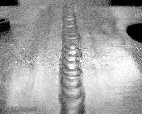
It may become critical for a particular weld, typically done by visual inspection, to be investigated with an extreme level of precision. Specific areas of interest for precise analysis include surface cracks, porosity and unfilled craters, regardless of subsequent inspection procedures. Weld characteristics such as dimension/shape, volume, roughness, size etc. can all be measured for critical evaluation.

IMPORTANCE OF 3D NON-CONTACT PROFILOMETER FOR WELD SURFACE INSPECTION

Unlike other techniques such as touch probes or interferometry, the NANOVEA 3D Non-Contact Profilometer, using axial chromatism, can measure nearly any surface, sample sizes can vary widely due to open staging and there is no sample preparation needed. Nano through macro range is obtained during surface profile measurement with zero influence from sample reflectivity or absorption, has advanced ability to measure high surface angles and there is no software manipulation of results. Easily measure any material: transparent, opaque, specular, diffusive, polished, rough etc. The 2D and 2D capabilities of the NANOVEA Portable Profilometers make them ideal instruments for full complete weld surface inspection both in the lab and in the field.

MEASUREMENT OBJECTIVE

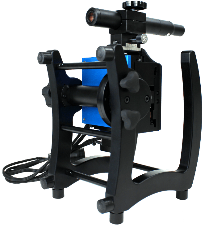
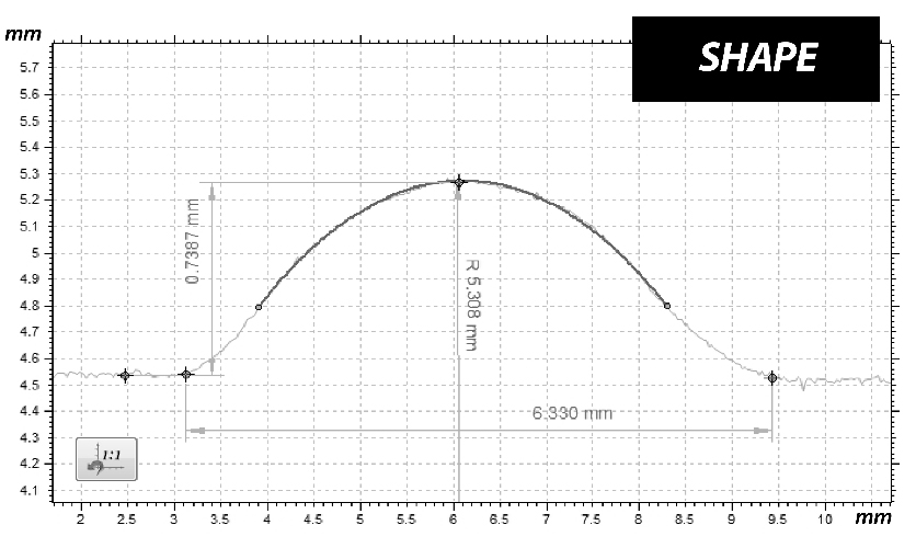
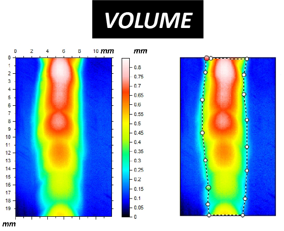
In this application, the NANOVEA JR25 Portable Profiler is used to measure the surface roughness, shape and volume of a weld, as well as the surrounding area. This information can provide critical information to properly investigate the quality of the weld and weld process.

NANOVEA

JR25

TEST RESULTS

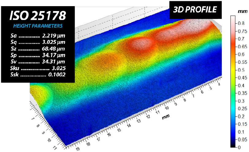
The image below shows the full 3D view of the weld and the surrounding area along with the surface parameters of the weld only. The 2D cross section profile is shown below.

the sample

With the above 2D cross section profile removed from the 3D, dimensional information of the weld is calculated below. Surface area and volume of material calculated for the weld only below.

 HOLEPEAK
SURFACE1.01 mm214.0 mm2
VOLUME8.799e-5 mm323.27 mm3
MAX DEPTH/HEIGHT0.0276 mm0.6195 mm
MEAN DEPTH/HEIGHT 0.004024 mm 0.2298 mm

CONCLUSION

In this application, we have shown how the NANOVEA 3D Non-Contact Profiler can precisely characterize critical characteristics of a weld and the surrounding surface area. From the roughness, dimensions and volume, a quantitative method for quality and repeatability can be determined and or further investigated. Sample welds, such as the example in this app note, can be easily analyzed, with a standard tabletop or portable NANOVEA Profiler for in-house or field testing

NOW, LET'S TALK ABOUT YOUR APPLICATION

Fiberglass Surface Topography Using 3D Profilometry

FIBERGLASS SURFACE TOPOGRAPHY

USING 3D PROFILOMETRY

Prepared by

CRAIG LEISING

INTRODUCTION

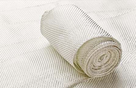
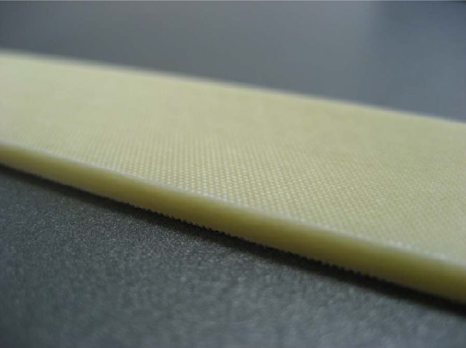
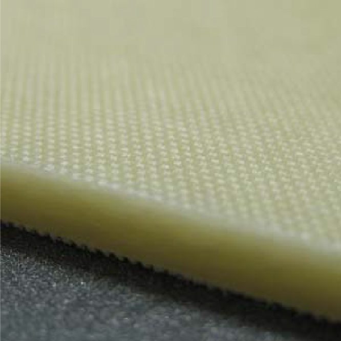
Fiberglass is a material made from extremely fine fibers of glass. It is used as a reinforcing agent for many polymer products; the resulting composite material, properly known as fiber-reinforced polymer (FRP) or glass-reinforced plastic (GRP), is called “fiberglass” in popular usage.

IMPORTANCE OF SURFACE METROLOGY INSPECTION FOR QUALITY CONTROL

Although there are many uses for Fiberglass reinforcement, in most applications it is crucial that they are as strong as possible. Fiberglass composites have one of the highest strength to weight ratios available and in some cases, pound for pound it is stronger than steel. Aside from high strength, it is also important to have the smallest possible exposed surface area. Large fiberglass surfaces can make the structure more vulnerable to chemical attack and possibly material expansion. Therefore, surface inspection is critical to quality control production.

MEASUREMENT OBJECTIVE

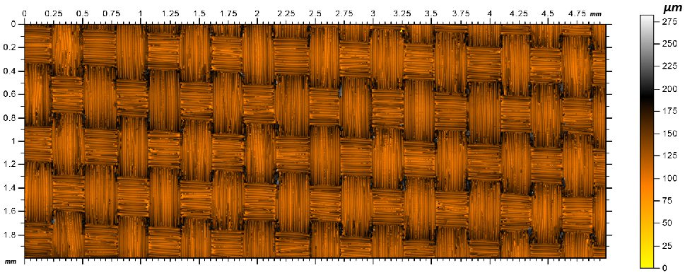
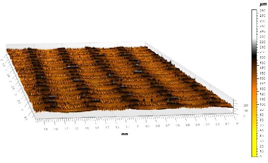
In this application, the NANOVEA ST400 is used to measure a Fiberglass Composite surface for roughness and flatness. By quantifying these surface features it is possible to create or optimize a stronger, longer lasting fiberglass composite material.

NANOVEA

ST400

MEASUREMENT PARAMETERS

PROBE 1 mm
ACQUISITION RATE300 Hz
AVERAGING1
MEASURED SURFACE5 mm x 2 mm
STEP SIZE5 µm x 5 µm
SCANNING MODEConstant speed

PROBE SPECIFICATIONS

MEASUREMENT RANGE1 mm
Z RESOLUTION 25 nm
Z ACCURACY200 nm
LATERAL RESOLUTION 2 μm

RESULTS

FALSE COLOR VIEW

3D Surface Flatness

3D Surface Roughness

Sa15.716 μmArithmetical Mean Height
Sq19.905 μmRoot Mean Square Height
Sp116.74 μmMaximum Peak Height
Sv136.09 μmMaximum Pit Height
Sz252.83 μmMaximum Height
Ssk0.556Skewness
Ssu3.654Kurtosis

CONCLUSION

As shown in the results, the NANOVEA ST400 Optical Profiler was able to accurately measure the roughness and flatness of the fiberglass composite surface. Data can be measured over multiple batches of fiber composites and or a given time period to provide crucial information about different fiberglass manufacturing processes and how they react over time. Thus, the ST400 is a viable option for strengthening the quality control process of fiberglass composite materials.

NOW, LET'S TALK ABOUT YOUR APPLICATION

Processed Leather Surface Finish using 3D Profilometry

PROCESSED LEATHER

SURFACE FINISH USING 3D PROFILOMETRY

Prepared by

CRAIG LEISING

INTRODUCTION

Once the tanning process of a leather hide is complete the leather surface can undergo several finishing processes for a variety of looks and touch. These mechanical processes can include stretching, buffing, sanding, embossing, coating etc. Dependent upon the end use of the leather some may require a more precise, controlled and repeatable processing.

IMPORTANCE OF PROFILOMETRY INSPECTION FOR R&D AND QUALITY CONTROL

Due to the large variation and unreliability of visual inspection methods, tools that are capable of accurately quantifying micro and nano scales features can improve leather finishing processes. Understanding the surface finish of leather in a quantifiable sense can lead to improved data driven surface processing selection to achieve optimal finish results. NANOVEA 3D Non-Contact Profilometers utilize chromatic confocal technology to measure finished leather surfaces and offer the highest repeatability and accuracy in the market. Where other techniques fail to provide reliable data, due to probe contact, surface variation, angle, absorption or reflectivity, NANOVEA Profilometers succeed.

MEASUREMENT OBJECTIVE

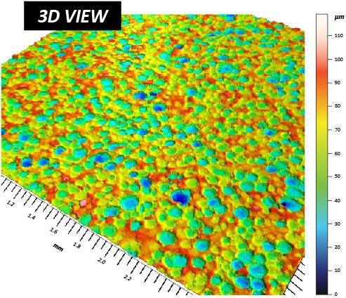
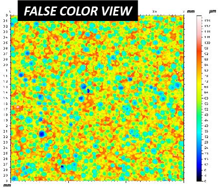
In this application, the NANOVEA ST400 is used to measure and compare the surface finish of two different but closely processed leather samples. Several surface parameters are automatically calculated from the surface profile.

Here we will focus on surface roughness, dimple depth, dimple pitch and dimple diameter for comparative evaluation.

NANOVEA

ST400

RESULTS: SAMPLE 1

ISO 25178

HEIGHT PARAMETERS

OTHER 3D PARAMETERS

RESULTS: SAMPLE 2

ISO 25178

HEIGHT PARAMETERS

OTHER 3D PARAMETERS

DEPTH COMPARATIVE

Depth distribution for each sample.
A large number of deep dimples were observed in
SAMPLE 1.

PITCH COMPARATIVE

Pitch between dimples on SAMPLE 1 is slightly smaller
than
SAMPLE 2, but both have a similar distribution

 MEAN DIAMETER COMPARATIVE

Similar distributions of mean diameter of dimples,
with
SAMPLE 1 showing slightly smaller mean diameters on average.

CONCLUSION

In this application, we have shown how the NANOVEA ST400 3D Profilometer can precisely characterize the surface finish of processed leather. In this study, having the ability to measure surface roughness, dimple depth, dimple pitch and dimple diameter allowed us to quantify differences between the finish and quality of the two samples that may not be obvious by visual inspection.

Overall there were no visible difference in the appearance of the 3D scans between SAMPLE 1 and SAMPLE 2. However, in the statistical analysis there is a clear distinction between the two samples. SAMPLE 1 contains a higher quantity of dimples with smaller diameters, larger depths and smaller dimple-to-dimple pitch in comparison to SAMPLE 2.

Please note that additional studies are available. Special areas of interest could have been further analyzed with an integrated AFM or Microscope module. NANOVEA 3D Profilometer speeds range from 20 mm/s to 1 m/s for laboratory or research to meet the needs of high-speed inspection; can be built with custom sizing, speeds, scanning capabilities, Class 1 clean room compliance, indexing conveyor or for in-line or online integration.

NOW, LET'S TALK ABOUT YOUR APPLICATION

Mechanical Properties of Hydrogel

MECHANICAL PROPERTIES OF HYDROGEL

USING NANOINDENTATION

Prepared by

DUANJIE LI, PhD & JORGE RAMIREZ

INTRODUCTION

Hydrogel is known for its super absorbency of water allowing for a close resemblance in flexibility as natural tissues. This resemblance has made hydrogel a common choice not only in biomaterials, but also in electronics, environment and consumer good applications such as contact lens. Each unique application requires specific hydrogel mechanical properties.

IMPORTANCE OF NANOINDENTATION FOR HYDROGEL

Hydrogels create unique challenges for Nanoindentation such as test parameters selection and sample preparation. Many nanoindentation systems have major limitations since they were not originally designed for such soft materials. Some of the nanoindentation systems use a coil/magnet assembly to apply force on the sample. There is no actual force measurement, leading to inaccurate and non-linear loading when testing soft materials. Determining the point of contact is extremely difficult as the depth is the only parameter actually being measured. It is almost impossible to observe the change of slope in the Depth vs Time plot during the period when the indenter tip is approaching the hydrogel material.

In order to overcome the limitations of these systems, the nano module of the NANOVEA Mechanical Tester measures the force feedback with an individual load cell to ensure high accuracy on all types of materials, soft or hard. The piezo-controlled displacement is extremely precise and fast. This allows unmatched measurement of viscoelastic properties by eliminating many theoretical assumptions that systems with a coil/magnet assembly and no force feedback must account for.

MEASUREMENT OBJECTIVE

In this application, the NANOVEA Mechanical Tester, in Nanoindentation mode, is used to study the hardness, elastic modulus and creep of a hydrogel sample.

NANOVEA

PB1000

TEST CONDITIONS

A hydrogel sample placed on a glass slide was tested by nanoindentation technique using a NANOVEA Mechanical Tester. For this soft material a 3 mm diameter spherical tip was used. The load linearly increased from 0.06 to 10 mN during the loading period. The creep was then measured by the change of indentation depth at the maximum load of 10 mN for 70 seconds.

APPROACH SPEED: 100 μm/min

CONTACT LOAD
0.06 mN
MAX LOAD
10 mN
LOADING RATE

20 mN/min

CREEP
70 s
RESULTS & DISCUSSION

The evolution of the load and depth as a function of time is shown in FUGURE 1. It can be observed that on the plot of the Depth vs Time, it is very difficult to determine the point of the change of slope at the beginning of the loading period, which usually works as an indication where the indenter starts to contact the soft material. However, the plot of the Load vs Time shows the peculiar behavior of the hydrogel under an applied load. As the hydrogel begins to get in touch with the ball indenter, the hydrogel pulls the ball indenter due to its surface tension, which tends to decrease the surface area. This behavior leads to the negative measured load at the beginning of the loading stage. The load progressively increases as the indenter sinks into the hydrogel, and it is then controlled to be constant at the maximum load of 10 mN for 70 seconds to study the creep behavior of the hydrogel.

FIGURE 1: Evolution of the load and depth as a function of Time.

The plot of the Creep Depth vs Time is shown in FIGURE 2, and the Load vs. Displacement plot of the nanoindentation test is shown in FIGURE 3. The hydrogel in this study possesses a hardness of 16.9 KPa and a Young’s modulus of 160.2 KPa, as calculated based on the load displacement curve using the Oliver-Pharr method.

Creep is an important factor for the study of a hydrogel’s mechanical properties. The close-loop feedback control between piezo and ultrasensitive load cell ensures a true constant loading during the creep time at the maximum load. As shown in FIGURE 2, the hydrogel subsides ~42 μm as a result of creep in 70 seconds under the 10 mN maximum load applied by the 3 mm ball tip.

FIGURE 2: Creeping at a max load of 10 mN for 70 seconds.

FIGURE 3: The Load vs. Displacement plot of the hydrogel.

CONCLUSION

In this study, we showcased that the NANOVEA Mechanical Tester, in Nanoindentation mode, provides a precise and repeatable measurement of a hydrogel’s mechanical properties including hardness, Young’s modulus and creep. The large 3 mm ball tip ensures proper contact against the hydrogel surface. The high precision motorized sample stage allows for accurate positioning of the flat face of the hydrogel sample under the ball tip. The hydrogel in this study exhibits a hardness of 16.9 KPa and a Young’s modulus of 160.2 KPa. The creep depth is ~42 μm under a 10 mN load for 70 seconds.

NANOVEA Mechanical Testers provide unmatched multi-function Nano and Micro modules on a single platform. Both modules include a scratch tester, hardness tester and a wear tester mode, offering the widest and the most user friendly range of testing available on a single
system.

NOW, LET'S TALK ABOUT YOUR APPLICATION

Piston Wear Testing

Piston Wear Testing

Using a Tribometer

Prepared by

FRANK LIU

INTRODUCTION

Friction loss accounts for approximately 10% of total energy in fuel for a diesel engine[1]. 40-55% of the friction loss comes from the power cylinder system. The loss of energy from friction can be diminished with better understanding of the tribological interactions occurring in the power cylinder system.

A significant portion of the friction loss in the power cylinder system stems from the contact between the piston skirt and the cylinder liner. The interaction between the piston skirt, lubricant, and cylinder interfaces is quite complex due to the constant changes in force, temperature, and speed in a real life engine. Optimizing each factor is key to obtaining optimal engine performance. This study will focus on replicating the mechanisms causing friction forces and wear at the piston skirt-lubricant-cylinder liner (P-L-C) interfaces.

 Schematic of power cylinders system and piston skirt-lubricant-cylinder liner interfaces.

[1] Bai, Dongfang. Modeling piston skirt lubrication in internal combustion engines. Diss. MIT, 2012

IMPORTANCE OF TESTING PISTONS WITH TRIBOMETERS

Motor oil is a lubricant that is well-designed for its application. In addition to the base oil, additives such as detergents, dispersants, viscosity improver (VI), anti-wear/anti-friction agents, and corrosion inhibitors are added to improve its performance. These additives affect how the oil behaves under different operating conditions. The behavior of oil affects the P-L-C interfaces and determines if significant wear from metal-metal contact or if hydrodynamic lubrication (very little wear) is occurring.

It is difficult to understand the P-L-C interfaces without isolating the area from external variables. It is more practical to simulate the event with conditions that are representative of its real-life application. The NANOVEA Tribometer is ideal for this. Equipped with multiple force sensors, depth sensor, a drop-by-drop lubricant module, and linear reciprocating stage, the NANOVEA T2000 is able to closely mimic events occurring within an engine block and obtain valuable data to better understand the P-L-C interfaces.

Liquid Module on the NANOVEA T2000 Tribometer

The drop-by-drop module is crucial for this study. Since pistons can move at a very fast rate (above 3000 rpm), it is difficult to create a thin film of lubricant by submerging the sample. To remedy this issue, the drop-by-drop module is able to consistently apply a constant amount of lubricant onto the piston skirt surface.

Application of fresh lubricant also removes concern of dislodged wear contaminants influencing the lubricant’s properties.

NANOVEA T2000

High Load Tribometer

MEASUREMENT OBJECTIVE

The piston skirt-lubricant-cylinder liner interfaces will be studied in this report. The interfaces will be replicated by conducting a linear reciprocating wear test with drop-by-drop lubricant module.

The lubricant will be applied at room temperature and heated conditions to compare cold start and optimal operation conditions. The COF and wear rate will be observed to better understand how the interfaces behaves in real-life applications.

TEST PARAMETERS

for tribology testing on pistons

LOAD ………………………. 100 N

TEST DURATION ………………………. 30 min

SPEED ………………………. 2000 rpm

AMPLITUDE ………………………. 10 mm

TOTAL DISTANCE ………………………. 1200 m

SKIRT COATING ………………………. Moly-graphite

PIN MATERIAL ………………………. Aluminum Alloy 5052

PIN DIAMETER ………………………. 10 mm

LUBRICANT ………………………. Motor Oil (10W-30)

APPROX. FLOW RATE ………………………. 60 mL/min

TEMPERATURE ………………………. Room temp & 90°C

LINEAR RECIPROCATING TEST RESULTS

In this experiment, A5052 was used as the counter material. While engine blocks are usually made of cast aluminum such as A356, A5052 have mechanical properties similar to A356 for this simulative testing [2].

Under the testing conditions, significant wear was
observed on the piston skirt at room temperature
compared to at 90°C. The deep scratches seen on the samples suggest that contact between the static material and the piston skirt occurs frequently throughout the test. The high viscosity at room temperature may be restricting the oil from completely filling gaps at the interfaces and creating metal-metal contact. At higher temperature, the oil thins and is able to flow between the pin and the piston. As a result, significantly less wear is observed at higher temperature. FIGURE 5 shows one side of the wear scar wore significantly less than the other side. This is most likely due to the location of the oil output. The lubricant film thickness was thicker on one side than the other, causing uneven wearing.


[2] “5052 Aluminum vs 356.0 Aluminum.” MakeItFrom.com, makeitfrom.com/compare/5052-O-Aluminum/A356.0-SG70B-A13560-Cast-Aluminum

The COF of linear reciprocating tribology tests can be split into a high and low pass. High pass refers to the sample moving in the forward, or positive, direction and low pass refers to the sample moving in the reverse, or negative, direction. The average COF for the RT oil was observed to be under 0.1 for both directions. The average COF between passes were 0.072 and 0.080. The average COF of the 90°C oil was found to be different between passes. Average COF values of 0.167 and 0.09 were observed. The difference in COF gives additional proof that the oil was only able to properly wet one side of the pin. High COF was obtained when a thick film was formed between the pin and the piston skirt due to hydrodynamic lubrication occurring. Lower COF is observed in the other direction when mixed lubrication is occurring. For more information on hydrodynamic lubrication and mixed lubrication, please visit our application note on Stribeck Curves.

Table 1: Results from lubricated wear test on pistons.

FIGURE 1: COF graphs for room temperature oil wear test A raw profile B high pass C low pass.

FIGURE 2: COF graphs for 90°C wear oil test A raw profile B high pass C low pass.

FIGURE 3: Optical image of wear scar from RT motor oil wear test.

FIGURE 4: Volume of a hole analysis of wear scar from RT motor oil wear test.

FIGURE 5: Profilometry scan of wear scar from RT motor oil wear test.

FIGURE 6: Optical image of wear scar from 90°C motor oil wear test

FIGURE 7: Volume of a hole analysis of wear scar from 90°C motor oil wear test.

FIGURE 8: Profilometry scan of wear scar from 90°C motor oil wear test.

CONCLUSION

Lubricated linear reciprocating wear testing was conducted on a piston to simulate events occurring in a
real-life operational engine. The piston skirt-lubricant-cylinder liner interfaces is crucial to the operations of an engine. The lubricant thickness at the interface is responsible for energy loss due to friction or wear between the piston skirt and cylinder liner. To optimize the engine, the film thickness must be as thin as possible without allowing the piston skirt and cylinder liner to touch. The challenge, however, is how changes in temperature, speed, and force will affect the P-L-C interfaces.

With its wide range of loading (up to 2000 N) and speed (up to 15000 rpm), the NANOVEA T2000 tribometer is able to simulate different conditions possible in an engine. Possible future studies on this topic include how the P-L-C interfaces will behave under different constant load, oscillated load, lubricant temperature, speed, and lubricant application method. These parameters can be easily adjusted with the NANOVEA T2000 tribometer to give a complete understanding on the mechanisms of the piston skirt-lubricant-cylinder liner interfaces.

NOW, LET'S TALK ABOUT YOUR APPLICATION

Organic Surface Topography using Portable 3D Profilometer


ORGANIC SURFACE TOPOGRAPHY

USING PORTABLE 3D PROFILOMETER

Prepared by

CRAIG LEISING

INTRODUCTION

Nature has become a vital pool of inspiration for the development of improved surface structure. Understanding the surface structures found in nature has led to adhesion studies based on gecko’s feet, resistance studies based on a sea cucumbers textural change and repellency studies based from leaves, among many others. These surfaces have a number of potential applications from biomedical to clothing and automotive. For any of these surface breakthroughs to be successful, fabrication techniques must be developed so surface characteristics can be mimicked and reproduced. It is this process that will require identification and control.

IMPORTANCE OF PORTABLE 3D NON-CONTACT OPTICAL PROFILER FOR ORGANIC SURFACES

Utilizing Chromatic Light technology, the NANOVEA Jr25 Portable Optical Profiler has superior capability to measure nearly any material. That includes the unique and steep angles, reflective and absorbing surfaces found within natures broad range of surface characteristics. 3D non-contact measurements provide a full 3D image to give a more complete understanding of surface features. Without 3D capabilities, identification of nature’s surfaces would be solely relying on 2D information or microscope imaging, which does not provide sufficient information to properly mimic the surface studied. Understanding the full range of the surface characteristics including texture, form, dimension, among many others, will be critical to successful fabrication.

The ability to easily obtain lab-quality results in the field opens the door for new research opportunities.

MEASUREMENT OBJECTIVE

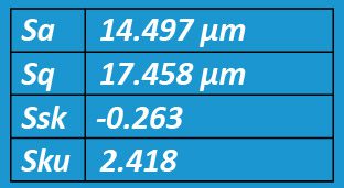
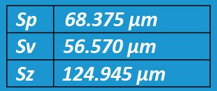
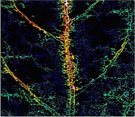
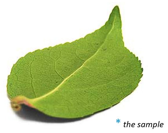
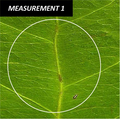
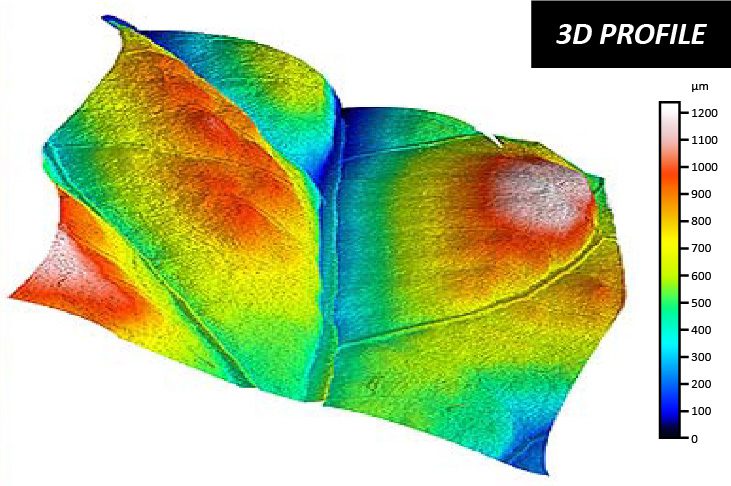
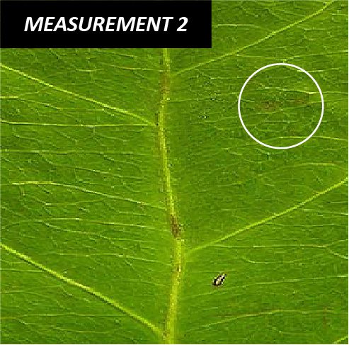
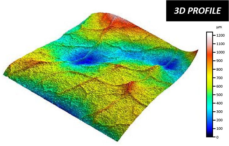
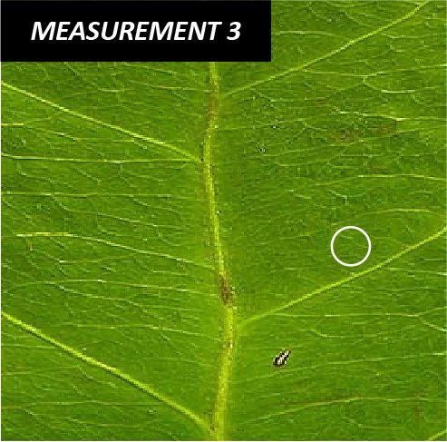
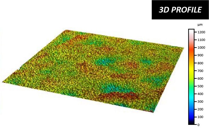
In this application, the NANOVEA Jr25 is used to measure the surface of a leaf. There is an endless list of surface parameters that can be automatically calculated after the 3D surface scan.

Here we will review the 3D surface and select
areas of interest to further analyze, including
quantifying and investigating the surface roughness, channels and topography

NANOVEA

JR25

TEST CONDITIONS

FURROW DEPTH

Mean density of furrows: 16.471 cm/cm2
Mean depth of furrows: 97.428 μm
Maximum depth: 359.769 μm

CONCLUSION

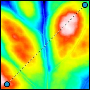
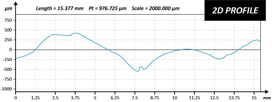
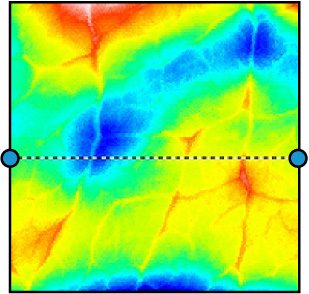
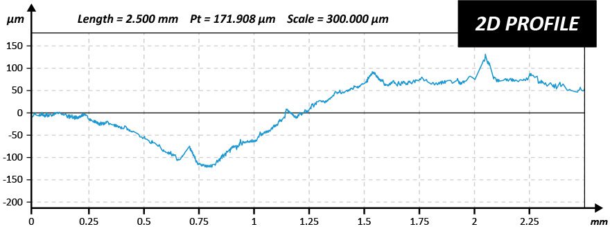
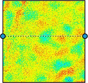
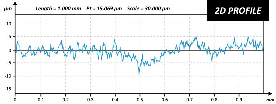
In this application, we have shown how the NANOVEA Jr25 portable 3D Non-Contact Optical Profiler can precisely characterize both the topography and the nanometer scale details of a leaf surface in the field. From these 3D surface measurements, areas of interest can quickly be identified and then analyzed with a list of endless studies (Dimension, Roughness Finish Texture, Shape Form Topography, Flatness Warpage Planarity, Volume Area, Step-Height and others). A 2D cross section can be easily chosen to analyze further details. With this information organic surfaces can be broadly investigated with a complete set of surface measurement resources. Special areas of interest could have been further analyzed with integrated AFM module on table top models.

NANOVEA also offers portable high-speed profilometers for field research and a wide range of lab-based systems, as well as provides laboratory services.

NOW, LET'S TALK ABOUT YOUR APPLICATION

Fresnel Lens Topography


FRESNEL LENS

DIMENSIONS USING 3D PROFILOMETRY

Prepared by

Duanjie Li & Benjamin Mell

INTRODUCTION

A lens is an optical device of axial symmetry that transmits and refracts light. A simple lens consists of a single optical component for converging or diverging the light. Even though spherical surfaces are not ideal shape for making a lens, they are often used as the simplest shape which glass can be ground and polished to.

A Fresnel lens consists of a series of concentric rings, which are thin parts of a simple lens with a width as small as a few thousandths of an inch. Fresnel lenses contain a large aperture and short focal length, with a compact design reducing the weight and volume of material required, compared to conventional lenses with the same optical properties. A very small amount of light is lost by absorption due to the thin geometry of the Fresnel lens.

IMPORTANCE OF 3D NON-CONTACT PROFILOMETRY FOR FRESNEL LENS INSPECTION

Fresnel lenses are extensively employed in the automotive industry, lighthouses, solar energy and optical landing systems for aircraft carriers. Molding or stamping the lenses out of transparent plastics can make their production cost-effective. Service quality of Fresnel lenses mostly depends on the precision and surface quality of their concentric ring. Unlike a touch probe technique, NANOVEA Optical Profilers perform 3D surface measurements without touching the surface, avoiding the risk of making new scratches. The Chromatic Light technique is ideal for precise scanning of complex shapes, such as lenses of different geometries.

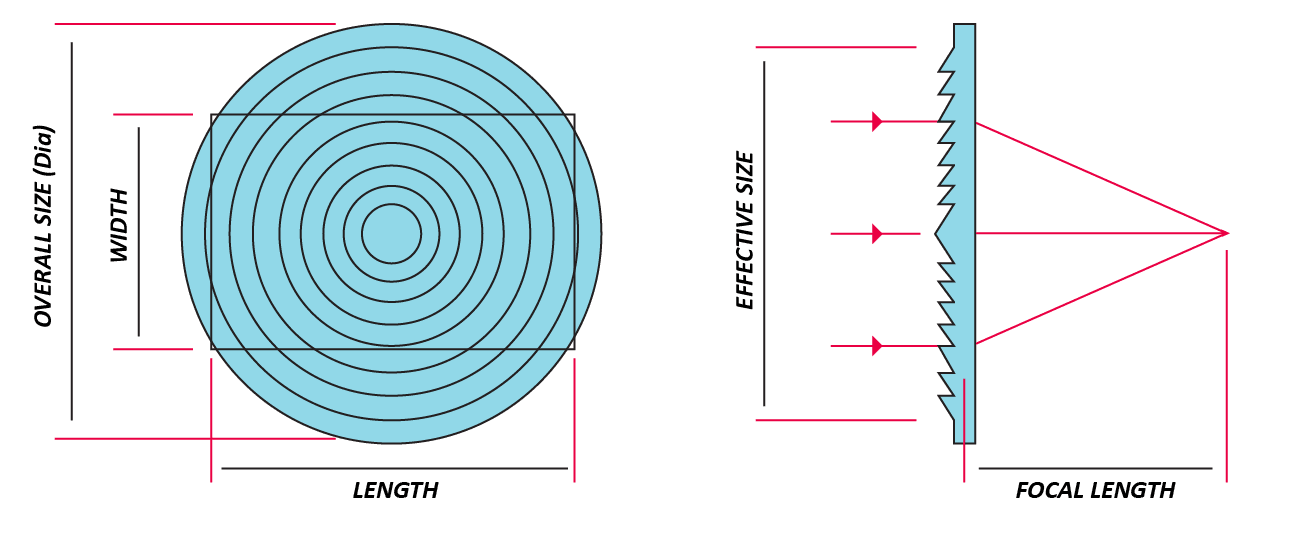
FRESNEL LENS SCHEMATIC

Transparent plastic Fresnel lenses can be manufactured by molding or stamping. Accurate and efficient quality control is critical to reveal defective production molds or stamps. By measuring the height and pitch of the concentric rings, production variations can be detected by comparing the measured values against the specification values given by the manufacturer of the lens.

Precise measurement of the lens profile ensures that the molds or stamps are properly machined to fit manufacturer specifications. Moreover, the stamp could progressively wear out over time, causing it to lose its initial shape. Consistent deviation from the lens manufacturer specification is a positive indication that the mold needs to be replaced.

MEASUREMENT OBJECTIVE

In this application, we showcase NANOVEA ST400, a 3D Non-Contact Profiler with a high-speed sensor, providing comprehensive 3D profile analysis of an optical component of a complex shape.To demonstrate the remarkable capabilities of our Chromatic Light technology, the contour analysis is performed on a Fresnel lens.

NANOVEA

ST400

The 2.3” x 2.3” acrylic Fresnel lens used for this study consists of 

a series of concentric rings and a complex serrated cross-section profile. 

It has a 1.5” focal length, 2.0” effective size diameter, 

125 grooves per inch, and an index of refraction of 1.49.

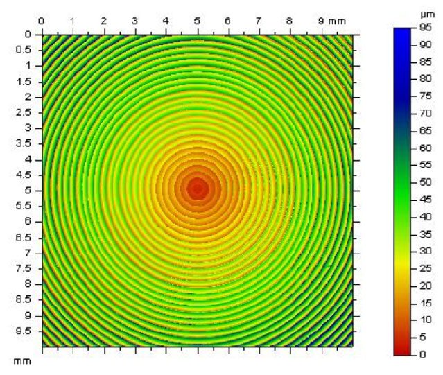
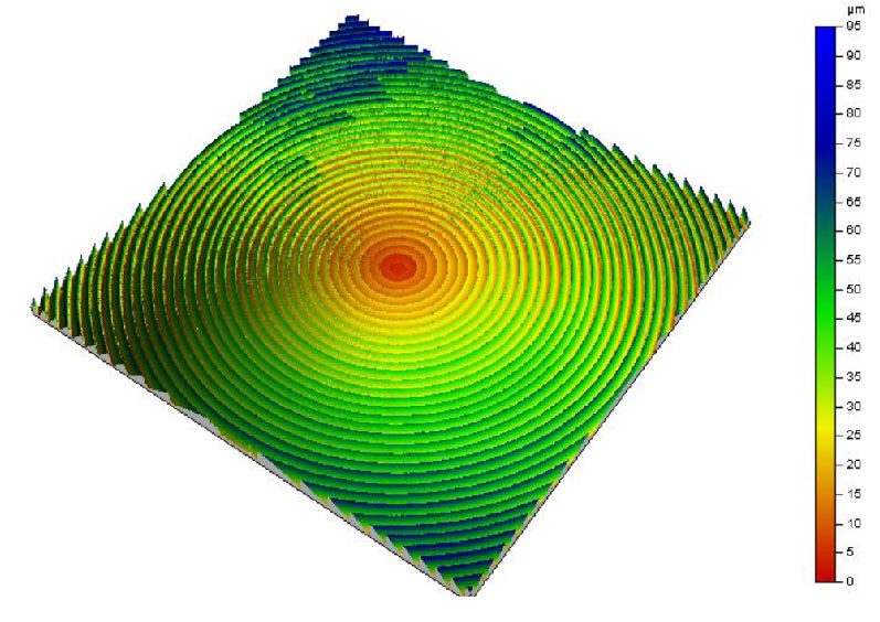
The NANOVEA ST400 scan of the Fresnel lens shows a noticeable increase in height of the concentric rings, moving outward from the center.

2D FALSE COLOR

Height Representation

3D VIEW

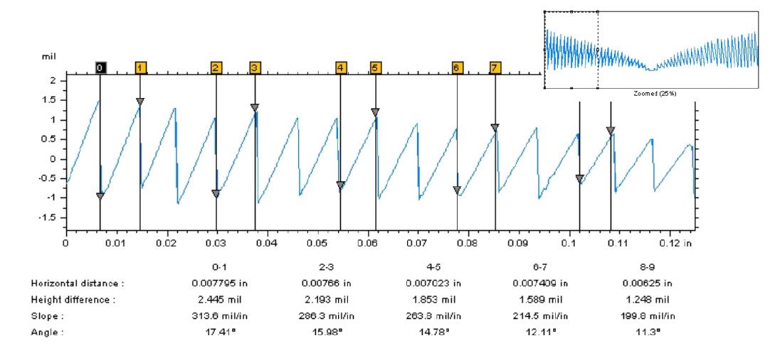
EXTRACTED PROFILE

PEAK & VALLEY

Dimensional Analysis of the Profile

CONCLUSION

In this application, we have showcased that the NANOVEA ST400 non-contact Optical Profiler accurately measures the surface topography of Fresnel lenses. 

The dimension of the height and pitch can be accurately determined from the complex serrated profile using NANOVEA analysis software. Users can effectively inspect the quality of the production molds or stamps by comparing the ring height and pitch dimensions of manufactured lenses against the ideal ring specification.

The data shown here represents only a portion of the calculations available in the analysis software. 

NANOVEA Optical Profilers measure virtually any surface in fields including Semiconductors, Microelectronics, Solar, Fiber Optics, Automotive, Aerospace, Metallurgy, Machining, Coatings, Pharmaceutical, Biomedical, Environmental and many others.


NOW, LET'S TALK ABOUT YOUR APPLICATION

Machined Parts QC

Machined Parts Inspection


MACHINED PARTS

inspection from CAD model using 3D profilometry

Author:

Duanjie Li, PhD

Revised by

Jocelyn Esparza

Machined Parts Inspection with a Profilometer

INTRODUCTION

The demand for precision machining able to create complex geometries has been on the rise across a spectrum of industries. From aerospace, medical and automobile, to tech gears, machinery and musical instruments, the continuous innovation and evolution push expectations and accuracy standards to new heights. Consequently, we see the rise of the demand for rigorous inspection techniques and instruments to ensure the highest quality of the products.

Importance of 3D Non-Contact Profilometry for Parts Inspection

Comparing properties of machined parts to their CAD models is essential to verify tolerances and adherence to production standards. Inspection during the service time is also crucial as wear and tear of the parts may call for their replacement. Identification of any deviations from the required specifications in a timely manner will help avoid costly repairs, production halts and tarnished reputation.

Unlike a touch probe technique, the NANOVEA Optical Profilers perform 3D surface scans with zero contact, allowing for quick, precise and non-destructive measurements of complex shapes with the highest accuracy.

MEASUREMENT OBJECTIVE

In this application, we showcase NANOVEA HS2000, a 3D Non-Contact Profiler with a high-speed sensor, performing a comprehensive surface inspection of dimension, radius, and roughness. 

All in under 40 seconds.

NANOVEA

HS2000

CAD MODEL

A precise measurement of the dimension and surface roughness of the machined part is critical to make sure it meets the desired specifications, tolerances and surface finishes. The 3D model and the engineering drawing of the part to be inspected are presented below. 

FALSE COLOR VIEW

The false color view of the CAD model and the scanned machined part surface are compared in FIGURE 3. The height variation on the sample surface can be observed by the change in color.

Three 2D profiles are extracted from the 3D surface scan as indicated in FIGURE 2 to further verify the dimensional tolerance of the machined part.

PROFILES COMPARISON & RESULTS

Profile 1 through 3 are shown in FIGURE 3 through 5. Quantitative tolerance inspection is carried out by comparing the measured profile with the CAD model to uphold rigorous manufacturing standards. Profile 1 and Profile 2 measure the radius of different areas on the curved machined part. The height variation of Profile 2 is 30 µm over a length of 156 mm which meets the desired ±125 µm tolerance requirement. 

By setting up a tolerance limit value, the analysis software can automatically determine pass or fail of the machined part.

Machine Parts Inspection with a Profilometer

The roughness and uniformity of the machined part’s surface play an important role in ensuring its quality and functionality. FIGURE 6 is an extracted surface area from the parent scan of the machined part which was used to quantify the surface finish. The average surface roughness (Sa) was calculated to be 2.31 µm.

CONCLUSION

In this study, we have showcased how the NANOVEA HS2000 Non-Contact Profiler equipped with a high speed sensor performs comprehensive surface inspection of dimensions and roughness. 

High-resolution scans enable users to measure detailed morphology and surface features of machined parts and to quantitatively compare them with their CAD models. The instrument is also capable of detecting any defects including scratches and cracks. 

The advanced contour analysis serves as an unparalleled tool not only to determine whether the machined parts satisfy the set specifications, but also to evaluate the failure mechanisms of the worn components.

The data shown here represents only a portion of the calculations possible with the advanced analysis software that comes equipped with every NANOVEA Optical Profiler.


NOW, LET'S TALK ABOUT YOUR APPLICATION

In-line Roughness Inspection

Instant Error Detection With In-Line Profilers

Learn more
 

IMPORTANCE OF NON-CONTACT PROFILER FOR IN-LINE ROUGHNESS INSPECTION

Surface defects derive from materials processing and product manufacturing. In-line surface quality inspection ensures the tightest quality control of the end products. The Nanovea 3D Non-Contact Profilometers utilize chromatic confocal technology with a unique capability to determine the roughness of a sample with-out contact. Multiple profiler sensors can be installed to monitor the roughness and texture of different areas of the product at the same time. The roughness threshold calculated in real-time by the analysis software serves as a fast and reliable pass/fail tool.


MEASUREMENT OBJECTIVE

In this study, the Nanovea roughness inspection conveyor system equipped with a point sensor is used to inspect the surface roughness of the acrylic and sandpaper samples. We showcase the capacity of Nanovea non-contact profilometer in providing fast and reliable in-line roughness inspection in a production line in real-time.


RESULTS AND DISCUSSION

The conveyor profilometer system can operate in two modes, namely Trigger Mode and Continuous Mode. As illustrated in Figure 2, the surface roughness of the samples are measured when they are passing under the optical profiler heads under the Trigger Mode. In comparison, Continuous Mode provides non-stop measurement of the surface roughness on the continuous sample, such as metal sheet and fabric. Multiple optical profiler sensors can be installed to monitor and record the roughness of different sample areas.


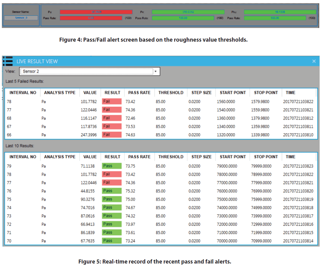
During the real-time roughness inspection measurement, the pass and fail alerts are displayed on the software windows as shown in Figure 4 and Figure 5. When the roughness value is within the given thresholds, the measured roughness is highlighted in green color. However, the highlight turns red when the measured surface roughness is out of the range of the set threshold values. This provides a tool for the user to determine the quality of a product’s surface finish.

In the following sections, two types of samples, e.g. Acrylic and Sandpaper are used to demonstrate the Trigger and Continuous Modes of the Inspection system.


Trigger Mode: Surface inspection of the Acrylic Sample

A series of Acrylic samples are aligned on the conveyor belt and move under the optical profiler head as shown in Figure 1. The false color view in Figure 6 shows the change of the surface height. Some of the mirror-like finished Acrylic samples had been sanded to create a rough surface texture as shown in Figure 6b.

As the Acrylic samples move at a constant speed under the optical profiler head, the surface profile is measured as shown in Figure 7 and Figure 8. The roughness value of the measured profile is calculated at the same time and compared to the threshold values. The red fail alert is launched when the roughness value is over the set threshold, allowing users to immediately detect and locate the defective product on the production line.
Continuous Mode: Surface Inspection of the sandpaper sample

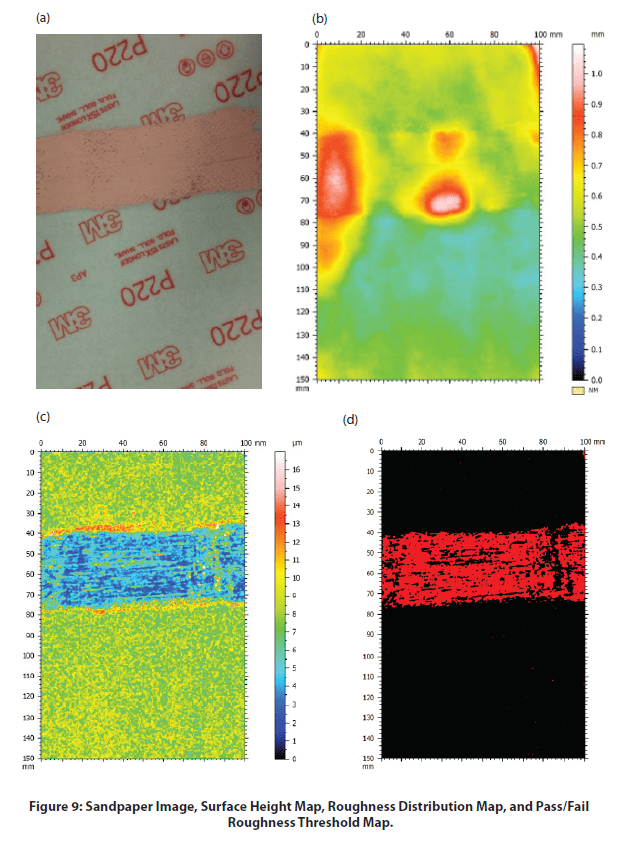
Surface Height Map, Roughness Distribution Map, and Pass / Fail Roughness Threshold Map of the sandpaper sample surface as shown in Figure 9. The sandpaper sample has a couple of higher peaks in the used part as shown in the surface height map. The different colors in the pallet of Figure 9C represent the roughness value of the local surface. The Roughness Map exhibits a homogeneous roughness in the intact area of the sandpaper sample, while the used area is highlighted in dark blue color, indicating the reduced roughness value in this region. A Pass/Fail roughness threshold can be set up to locate such regions as shown in Figure 9D.

As the sandpaper continuously passes under the in-line profiler sensor, the real-time local roughness value is calculated and recorded as plotted in Figure 10. The pass/fail alerts are displayed on the software screen based on the set roughness threshold values, serving as a fast and reliable tool for quality control. The product surface quality in the production line is inspected in situ to discover defective areas in time.


CONCLUSION


In this application, we have shown the Nanovea Conveyor Profilometer equipped with an optical non-contact profiler sensor works as a reliable in-line quality control tool effectively and efficiently.

The inspection system can be installed in the production line to monitor the surface quality of the products in situ. The roughness threshold works as a dependable criteria to determine the surface quality of the products, allowing users to notice the defective products in time. Two inspection modes, namely Trigger Mode and Continuous Mode, are provided to meet the requirement for inspection on different types of products.

The data shown here represent only a portion of the calculations available in the analysis software. Nanovea Profilometers measure virtually any surface in fields including Semiconductor, Microelectronics, Solar, Fiber, Optics, Automotive, Aerospace, Metallurgy, Machining, Coatings, Pharmaceutical, Biomedical, Environmental and many others.
NOW, LET'S TALK ABOUT YOUR APPLICATION