Monthly Archives: September 2020

Machined Parts Inspection


MACHINED PARTS
inspection from CAD model using 3D profilometry
Author:
Duanjie Li, PhD
Revised by
Jocelyn Esparza

INTRODUCTION
The demand for precision machining able to create complex geometries has been on the rise across a spectrum of industries. From aerospace, medical and automobile, to tech gears, machinery and musical instruments, the continuous innovation and evolution push expectations and accuracy standards to new heights. Consequently, we see the rise of the demand for rigorous inspection techniques and instruments to ensure the highest quality of the products.
Importance of 3D Non-Contact Profilometry for Parts Inspection
Comparing properties of machined parts to their CAD models is essential to verify tolerances and adherence to production standards. Inspection during the service time is also crucial as wear and tear of the parts may call for their replacement. Identification of any deviations from the required specifications in a timely manner will help avoid costly repairs, production halts and tarnished reputation.
Unlike a touch probe technique, the NANOVEA Optical Profilers perform 3D surface scans with zero contact, allowing for quick, precise and non-destructive measurements of complex shapes with the highest accuracy.
MEASUREMENT OBJECTIVE
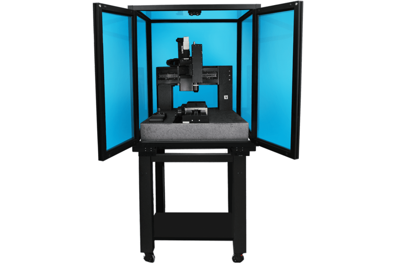
In this application, we showcase NANOVEA HS2000, a 3D Non-Contact Profiler with a high-speed sensor, performing a comprehensive surface inspection of dimension, radius, and roughness.
All in under 40 seconds.
NANOVEA
HS2000
CAD MODEL
A precise measurement of the dimension and surface roughness of the machined part is critical to make sure it meets the desired specifications, tolerances and surface finishes. The 3D model and the engineering drawing of the part to be inspected are presented below.

FALSE COLOR VIEW
The false color view of the CAD model and the scanned machined part surface are compared in FIGURE 3. The height variation on the sample surface can be observed by the change in color.
Three 2D profiles are extracted from the 3D surface scan as indicated in FIGURE 2 to further verify the dimensional tolerance of the machined part.

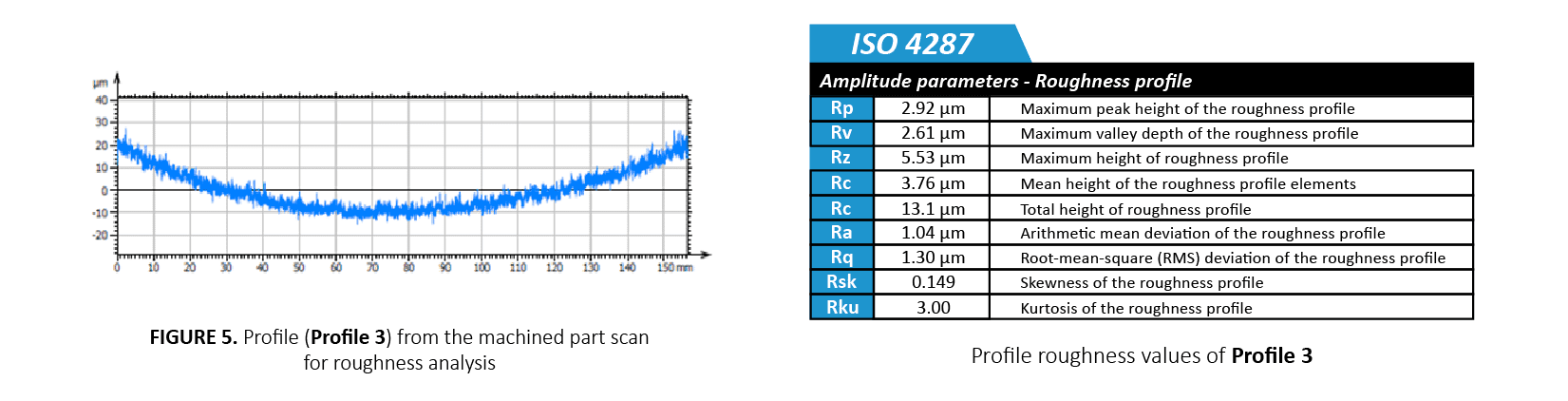
PROFILES COMPARISON & RESULTS
Profile 1 through 3 are shown in FIGURE 3 through 5. Quantitative tolerance inspection is carried out by comparing the measured profile with the CAD model to uphold rigorous manufacturing standards. Profile 1 and Profile 2 measure the radius of different areas on the curved machined part. The height variation of Profile 2 is 30 µm over a length of 156 mm which meets the desired ±125 µm tolerance requirement.
By setting up a tolerance limit value, the analysis software can automatically determine pass or fail of the machined part.

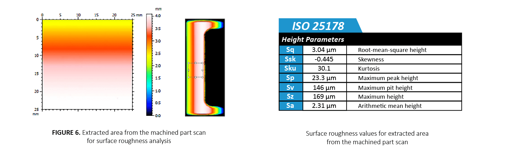
The roughness and uniformity of the machined part’s surface play an important role in ensuring its quality and functionality. FIGURE 6 is an extracted surface area from the parent scan of the machined part which was used to quantify the surface finish. The average surface roughness (Sa) was calculated to be 2.31 µm.
CONCLUSION
In this study, we have showcased how the NANOVEA HS2000 Non-Contact Profiler equipped with a high speed sensor performs comprehensive surface inspection of dimensions and roughness.
High-resolution scans enable users to measure detailed morphology and surface features of machined parts and to quantitatively compare them with their CAD models. The instrument is also capable of detecting any defects including scratches and cracks.
The advanced contour analysis serves as an unparalleled tool not only to determine whether the machined parts satisfy the set specifications, but also to evaluate the failure mechanisms of the worn components.
The data shown here represents only a portion of the calculations possible with the advanced analysis software that comes equipped with every NANOVEA Optical Profiler.

Fretting Wear Evaluation
FRETTING WEAR EVALUATION

Author:
Duanjie Li, PhD
Revised by
Jocelyn Esparza

INTRODUCTION
Fretting is “a special wear process that occurs at the contact area between two materials under load and subject to minute relative motion by vibration or some other force.” When machines are in operation, vibrations inevitably occur in joints that are bolted or pinned, between components that are not intended to move, and in oscillating couplings and bearings. The amplitude of such relative sliding motion is often in the order of micrometers to millimeters. Such repetitive low-amplitude motion causes serious localized mechanical wear and material transfer at the surface, which may lead to reduced production efficiency, machine performance or even damage to the machine.
Importance of Quantitative
Fretting Wear Evaluation
Fretting wear often involves several complex wear mechanisms taking place at the contact surface, including two-body abrasion, adhesion and/or fretting fatigue wear. In order to understand the fretting wear mechanism and select the best material for fretting wear protection, reliable and quantitative fretting wear evaluation is needed. The fretting wear behavior is significantly influenced by the work environment, such as displacement amplitude, normal loading, corrosion, temperature, humidity and lubrication. A versatile tribometer that can simulate the different realistic work conditions will be ideal for fretting wear evaluation.
Steven R. Lampman, ASM Handbook: Volume 19: Fatigue and Fracture
http://www.machinerylubrication.com/Read/693/fretting-wear
MEASUREMENT OBJECTIVE
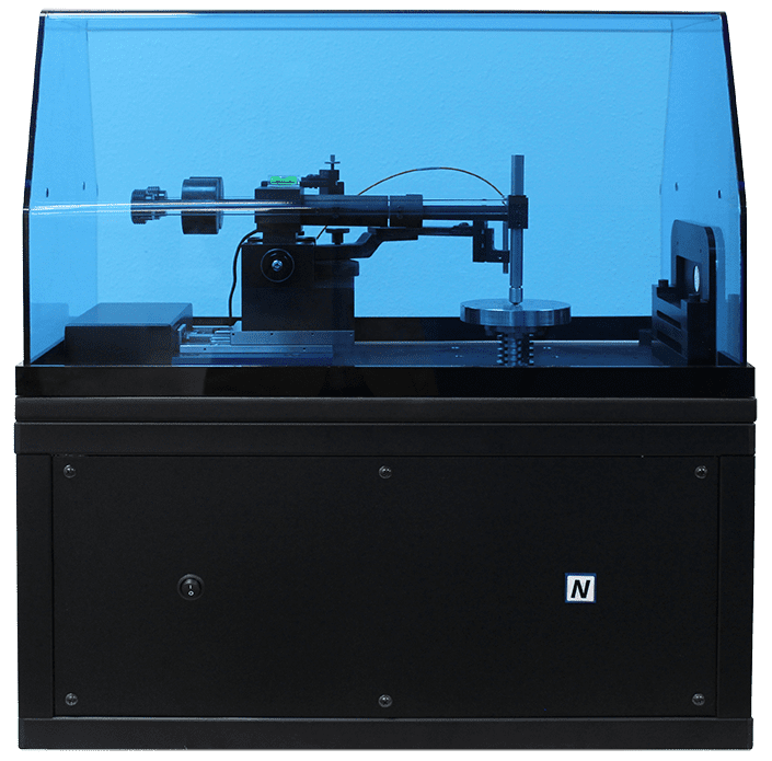
In this study, we evaluated the fretting wear behaviors of a stainless steel SS304 sample at different oscillation speeds and temperatures to showcase the capacity of NANOVEA T50 Tribometer in simulating the fretting wear process of metal in a well-controlled and monitored manner.
NANOVEA
T50
TEST CONDITIONS
The fretting wear resistance of a stainless steel SS304 sample was evaluated by NANOVEA Tribometer using Linear Reciprocating Wear Module. A WC (6 mm diameter) ball was used as the counter material. The wear track was examined using a NANOVEA 3D non-contact profiler.
The fretting test was performed at room temperature (RT) and 200 °C to study the effect of high temperature on the fretting wear resistance of the SS304 sample. A heating plate on the sample stage heated up the sample during the fretting test at 200 °C. The wear rate, K, was evaluated using the formula K=V/(F×s), where V is the worn volume, F is the normal load, and s is the sliding distance.
Please note that a WC ball as a counter material was used as an example in this study. Any solid material with different shapes and surface finish can be applied using a custom fixture to simulate the actual application situation.
TEST PARAMETERS
of the wear measurements

RESULTS & DISCUSSION
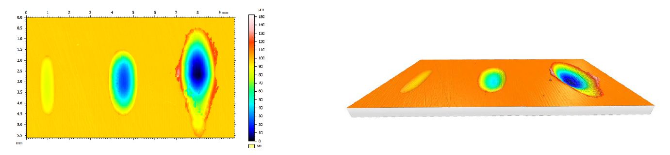
The 3D wear track profile allows direct and accurate determination of the wear track volume loss calculated by the NANOVEA Mountains analysis software.
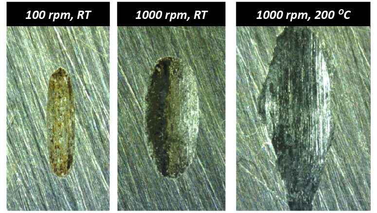
The reciprocating wear test at a low speed of 100 rpm and room temperature exhibits a small wear track of 0.014 mm³. In comparison, the fretting wear test carried out at a high speed of 1000 rpm creates a substantially larger wear track with a volume of 0.12 mm³. Such an accelerated wear process may be attributed to the high heat and intense vibration generated during the fretting wear test, which promotes oxidation of the metallic debris and results in severe three-body abrasion. The fretting wear test at an elevated temperature of 200 °C forms a larger wear track of 0.27 mm³.
The fretting wear test at 1000 rpm has a wear rate of 1.5×10⁻⁴ mm³/Nm, which is nearly nine times compared to that in a reciprocating wear test at 100 rpm. The fretting wear test at an elevated temperature further accelerates the wear rate to 3.4×10⁻⁴ mm³/Nm. Such a significant difference in wear resistance measured at different speeds and temperatures shows the importance of proper simulations of fretting wear for realistic applications.
Wear behavior can change drastically when small changes in testing conditions are introduced into the tribosystem. The versatility of the NANOVEA Tribometer allows measuring wear under various conditions, including high temperature, lubrication, corrosion and others. The accurate speed and position control by the advanced motor enables users to perform the wear test at speeds ranging from 0.001 to 5000 rpm, making it an ideal tool for research/testing labs to investigate the fretting wear in different tribological conditions.
Fretting wear tracks at various conditions
under the optical microscope
3D WEAR TRACKs PROFILES
provide more insight in fundamental understanding
of the fretting wear mechanism
RESULT SUMMARY OF WEAR TRACKS
measured using different test parameters

CONCLUSION
In this study, we showcased the capacity of the NANOVEA Tribometer in evaluating the fretting wear behavior of a stainless steel SS304 sample in a well-controlled and quantitative manner.
The test speed and temperature play critical roles in the fretting wear resistance of the materials. The high heat and intense vibration during the fretting resulted in substantially accelerated wear of the SS304 sample by close to nine times. The elevated temperature of 200 °C further increased the wear rate to 3.4×10⁻⁴ mm3/Nm.
The versatility of the NANOVEA Tribometer makes it an ideal tool for measuring fretting wear under various conditions, including high temperature, lubrication, corrosion and others.
NANOVEA Tribometers offer precise and repeatable wear and friction testing using ISO and ASTM compliant rotative and linear modes, with optional high temperature wear, lubrication and tribo-corrosion modules available in one pre-integrated system. Our unmatched range is an ideal solution for determining the full scope of tribological properties of thin or thick, soft or hard coatings, films and substrates.
Categories
- Application Notes
- Block on Ring Tribology
- Corrosion Tribology
- Friction Testing | Coefficient of Friction
- High Temperature Mechanical Testing
- High Temperature Tribology
- Humidity and Gases Tribology
- Humidity Mechanical Testing
- Indentation | Creep and Relaxation
- Indentation | Fracture Toughness
- Indentation | Hardness and Elastic
- Indentation | Loss and Storage
- Indentation | Stress vs Strain
- Indentation | Yield Strength and Fatigue
- Laboratory Testing
- Linear Tribology
- Liquid Mechanical Testing
- Liquid Tribology
- Low Temperature Tribology
- Mechanical Testing
- Press Release
- Profilometry | Flatness and Warpage
- Profilometry | Geometry and Shape
- Profilometry | Roughness and Finish
- Profilometry | Step Height and Thickness
- Profilometry | Texture and Grain
- Profilometry | Volume and Area
- Profilometry Testing
- Ring on Ring Tribology
- Rotational Tribology
- Scratch Testing | Adhesive Failure
- Scratch Testing | Cohesive Failure
- Scratch Testing | Multi-Pass Wear
- Scratch Testing | Scratch Hardness
- Scratch Testing Tribology
- Tribology Testing
- Uncategorized
Archives
- June 2026
- May 2026
- March 2026
- November 2025
- September 2023
- August 2023
- June 2023
- May 2023
- July 2022
- May 2022
- April 2022
- January 2022
- December 2021
- November 2021
- October 2021
- September 2021
- August 2021
- July 2021
- June 2021
- May 2021
- March 2021
- February 2021
- December 2020
- November 2020
- October 2020
- September 2020
- July 2020
- May 2020
- April 2020
- March 2020
- February 2020
- January 2020
- November 2019
- October 2019
- September 2019
- August 2019
- July 2019
- June 2019
- May 2019
- April 2019
- March 2019
- January 2019
- December 2018
- November 2018
- October 2018
- September 2018
- July 2018
- June 2018
- April 2018
- March 2018
- February 2018
- November 2017
- October 2017
- September 2017
- August 2017
- June 2017
- May 2017
- March 2017
- February 2017
- January 2017
- November 2016
- October 2016
- August 2016
- July 2016
- June 2016
- May 2016
- April 2016
- March 2016
- February 2016
- January 2016
- December 2015
- November 2015
- October 2015
- September 2015
- August 2015
- July 2015
- June 2015
- May 2015
- April 2015
- March 2015
- February 2015
- January 2015
- November 2014
- October 2014
- September 2014
- August 2014
- July 2014
- June 2014
- May 2014
- April 2014
- March 2014
- February 2014
- January 2014
- December 2013
- November 2013
- October 2013
- September 2013
- August 2013
- July 2013
- June 2013
- May 2013
- April 2013
- March 2013
- February 2013
- January 2013
- December 2012
- November 2012
- October 2012
- September 2012
- August 2012
- July 2012
- June 2012
- May 2012
- April 2012
- March 2012
- February 2012
- January 2012
- December 2011
- November 2011
- October 2011
- September 2011
- August 2011
- July 2011
- June 2011
- May 2011
- November 2010
- January 2010
- April 2009
- March 2009
- January 2009
- December 2008
- October 2008
- August 2007
- July 2006
- March 2006
- January 2005
- April 2004


