USA/GLOBAL: +1-949-461-9292
EUROPE: +39-011-3052-794
CONTACT US

Industrial Coatings Scratch and Wear Evaluation

INDUSTRIAL COATING

SCRATCH AND WEAR EVALUATION USING A TRIBOMETER

Prepared by

DUANJIE LI, PhD & ANDREA HERRMANN

INTRODUCTION

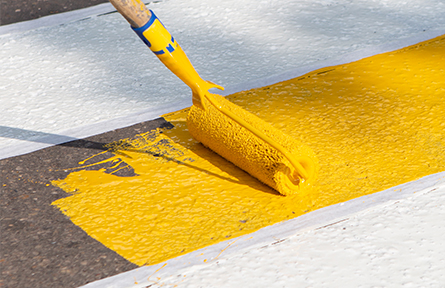
Acrylic urethane paint is a type of fast-dry protective coating widely used in a variety of industrial applications, such as floor paint, auto paint, and others. When used as floor paint, it can serve areas with heavy foot and rubber-wheel traffic, such as walkways, curbs and parking lots.

IMPORTANCE OF SCRATCH AND WEAR TESTING FOR QUALITY CONTROL

Traditionally, Taber abrasion tests were carried out to evaluate the wear resistance of acrylic urethane floor paint according to the ASTM D4060 standard. However, as mentioned in the standard, “For some materials, abrasion tests utilizing the Taber Abraser may be subject to variation due to changes in the abrasive characteristics of the wheel during testing.”1 This may result in poor reproducibility of test results and create difficulty in comparing values reported from different laboratories. Moreover, in Taber abrasion tests, abrasion resistance is calculated as loss in weight at a specified number of abrasion cycles. However, acrylic urethane floor paints have a recommended dry film thickness of 37.5-50 μm2.

The aggressive abrasion process by Taber Abraser can quickly wear through the acrylic urethane coating and create mass loss to the substrate leading to substantial errors in the calculation of the paint weight loss. The implant of abrasive particles in the paint during the abrasion test also contributes to errors. Therefore, a well-controlled quantifiable and reliable measurement is crucial to ensure reproducible wear evaluation of the paint. In addition, the scratch test allows users to detect premature adhesive/cohesive failures in real-life applications.

MEASUREMENT OBJECTIVE

In this study, we showcase that NANOVEA Tribometers and Mechanical Testers are ideal for evaluation and quality control of industrial coatings.

The wear process of acrylic urethane floor paints with different topcoats is simulated in a controlled and monitored manner using the NANOVEA Tribometer. Micro scratch testing is used to measure the load required to cause cohesive or adhesive failure to the paint.

NANOVEA T100

The Compact Pneumatic Tribometer

NANOVEA PB1000

The Large Platform Mechanical Tester

TEST PROCEDURE

This study evaluates four commercially available water-based acrylic floor coatings that have the same primer (basecoat) and different topcoats of the same formula with a small alternation in the additive blends for the purpose of enhancing durability. These four coatings are identified as Samples A, B, C and D.

WEAR TEST

The NANOVEA Tribometer was applied to evaluate the tribological behavior, e.g. coefficient of friction, COF, and wear resistance. A SS440 ball tip (6 mm dia., Grade 100) was applied against the tested paints. The COF was recorded in situ. The wear rate, K, was evaluated using the formula K=V/(F×s)=A/(F×n), where V is the worn volume, F is the normal load, s is the sliding distance, A is the cross-sectional area of the wear track, and n is the number of revolution. Surface roughness and wear track profiles were evaluated by the NANOVEA Optical Profilometer, and the wear track morphology was examined using optical microscope.

WEAR TEST PARAMETERS

NORMAL FORCE

20 N

SPEED

15 m/min

DURATION OF TEST

100, 150, 300 & 800 cycles

SCRATCH TEST

The NANOVEA Mechanical Tester equipped with a Rockwell C diamond stylus (200 μm radius) was used to perform progressive load scratch tests on the paint samples using the Micro Scratch Tester Mode. Two final loads were used: 5 N final load for investigating paint delamination from the primer, and 35 N for investigating primer delamination from the metal substrates. Three tests were repeated at the same testing conditions on each sample to ensure reproducibility of the results.

Panoramic images of the whole scratch lengths were automatically generated and their critical failure locations were correlated with the applied loads by the system software. This software feature facilitates users to perform analysis on the scratch tracks any time, rather than having to determine the critical load under the microscope immediately after the scratch tests.

SCRATCH TEST PARAMETERS

LOAD TYPEProgressive
INITIAL LOAD0.01 mN
FINAL LOAD5 N / 35 N
LOADING RATE10 / 70 N/min
SCRATCH LENGTH3 mm
SCRATCHING SPEED, dx/dt6.0 mm/min
INDENTER GEOMETRY120º cone
INDENTER MATERIAL (tip)Diamond
INDENTER TIP RADIUS200 μm

WEAR TEST RESULTS

Four pin-on-disk wear tests at different number of revolutions (100, 150, 300 and 800 cycles) were performed on each sample in order to monitor the evolution of wear. The surface morphology of the samples were measured with a NANOVEA 3D Non-Contact Profiler to quantify the surface roughness prior to conducting wear testing. All samples had a comparable surface roughness of approximately 1 μm as displayed in FIGURE 1. The COF was recorded in situ during the wear tests as shown in FIGURE 2. FIGURE 4 presents the evolution of wear tracks after 100, 150, 300 and 800 cycles, and FIGURE 3 summarized the average wear rate of different samples at different stages of the wear process.


Compared with a COF value of ~0.07 for the other three samples, Sample A exhibits a much higher COF of ~0.15 at the beginning, which gradually increases and gets stable at ~0.3 after 300 wear cycles. Such a high COF accelerates the wear process and creates a substantial amount of paint debris as indicated in FIGURE 4 – the topcoat of Sample A has started to be removed in the first 100 revolutions. As shown in FIGURE 3, Sample A exhibits the highest wear rate of ~5 μm2/N in the first 300 cycles, which slightly decreases to ~3.5 μm2/N due to the better wear resistance of the metal substrate. The topcoat of Sample C starts to fail after 150 wear cycles as shown in FIGURE 4, which is also indicated by the increase of COF in FIGURE 2.


In comparison, Sample B and Sample D show enhanced tribological properties. Sample B maintains a low COF throughout the whole test – the COF slightly increases from~0.05 to ~0.1. Such a lubricating effect substantially enhances its wear resistance – the topcoat still provides superior protection to the primer underneath after 800 wear cycles. The lowest average wear rate of only ~0.77 μm2/N is measured for Sample B at 800 cycles. The topcoat of Sample D starts to delaminate after 375 cycles, as reflected by the abrupt increase of COF in FIGURE 2. The average wear rate of Sample D is ~1.1 μm2/N at 800 cycles.


Compared to the conventional Taber abrasion measurements, NANOVEA Tribometer provides well-controlled quantifiable and reliable wear assessments that ensure reproducible evaluations and quality control of commercial floor/auto paints. Moreover, the capacity of in situ COF measurements allow users to correlate the different stages of a wear process with the evolution of COF, which is critical in improving fundamental understanding of the wear mechanism and tribological characteristics of various paint coatings.

FIGURE 1: 3D morphology and roughness of the paint samples.

FIGURE 2: COF during pin-on-disk tests.

FIGURE 3: Evolution of wear rate of different paints.

FIGURE 4: Evolution of wear tracks during the pin-on-disk tests.

WEAR TEST RESULTS

FIGURE 5 shows the plot of normal force, frictional force and true depth as a function of scratch length for Sample A as an example. An optional acoustic emission module can be installed to provide more information. As the normal load linearly increases, the indentation tip gradually sinks into the tested sample as reflected by the progressive increase of true depth. The variation in the slopes of frictional force and true depth curves can be used as one of the implications that coating failures start to occur.

FIGURE 5: Normal force, frictional force and true depth as a function of scratch length for scratch test of Sample A with a maximum load of 5 N.

FIGURE 6 and FIGURE 7 show the full scratches of all four paint samples tested with a maximum load of 5 N and 35 N, respectively. Sample D required a higher load of 50 N to delaminate the primer. Scratch tests at 5 N final load (FIGURE 6) evaluate the cohesive/adhesive failure of the top paint, while the ones at 35 N (FIGURE 7) assess the delamination of the primer. The arrows in the micrographs indicate the point at which the top coating or the primer start to be completely removed from the primer or the substrate. The load at this point, so called Critical Load, Lc, is used to compare the cohesive or adhesive properties of the paint as summarized in Table 1.


It is evident that the paint Sample D has the best interfacial adhesion – exhibiting the highest Lc values of 4.04 N at paint delamination and 36.61 N at primer delamination. Sample B shows the second best scratch resistance. From the scratch analysis, we show that optimization of the paint formula is critical to the mechanical behaviors, or more specifically, scratch resistance and adhesion property of acrylic floor paints.

Table 1: Summary of critical loads.

FIGURE 6: Micrographs of full scratch with 5 N maximum load.

FIGURE 7: Micrographs of full scratch with 35 N maximum load.

CONCLUSION

Compared to the conventional Taber abrasion measurements, the NANOVEA Mechanical Tester and Tribometer are superior tools for evaluation and quality control of commercial floor and automotive coatings. The NANOVEA Mechanical Tester in Scratch mode can detect adhesion/cohesion problems in a coating system. The NANOVEA Tribometer provides well-controlled quantifiable and repeatable tribological analysis on wear resistance and coefficient of friction of the paints.


Based on the comprehensive tribological and mechanical analyses on the water based acrylic floor coatings tested in this study, we show that Sample B possesses the lowest COF and wear rate and the second best scratch resistance, while Sample D exhibits the best scratch resistance and second best wear resistance. This assessment allows us to evaluate and select the best candidate targeting the needs in different application environments.


The Nano and Micro modules of the NANOVEA Mechanical Tester all include ISO and ASTM compliant indentation, scratch and wear tester modes, providing the widest range of testing available for paint evaluation on a single module. The NANOVEA Tribometer offers precise and repeatable wear and friction testing using ISO and ASTM compliant rotative and linear modes, with optional high temperature wear, lubrication and tribo-corrosion modules available in one pre-integrated system. NANOVEA’s unmatched range is an ideal solution for determining the full range of mechanical/tribological properties of thin or thick, soft or hard coatings, films and substrates, including hardness, Young’s modulus, fracture toughness, adhesion, wear resistance and many others. Optional NANOVEA Non-Contact Optical Profilers are available for high resolution 3D imaging of scratchs and wear tracks in addition to other surface measurements such as roughness.

NOW, LET'S TALK ABOUT YOUR APPLICATION

Scratch Hardness Measurement using Mechanical Tester

SCRATCH HARDNESS MEASUREMENT

USING A MECHANICAL TESTER

Prepared by

DUANJIE LI, PhD

INTRODUCTION

In general, hardness tests measure the resistance of materials to permanent or plastic deformation. There are three types of hardness measurements: scratch hardness, indentation hardness and rebound hardness. A scratch hardness test measures a material’s resistance to scratch and abrasion due to friction from a sharp object1. It was originally developed by German mineralogist Friedrich Mohs in 1820 and is still widely used to rank the physical properties of minerals2. This test method is also applicable to metals, ceramics, polymers, and coated surfaces.

During a scratch hardness measurement, a diamond stylus of specified geometry scratches into a material’s surface along a linear path under a constant normal force with a constant speed. The average width of the scratch is measured and used to calculate the scratch hardness number (HSP). This technique provides a simple solution for scaling the hardness of different materials.

MEASUREMENT OBJECTIVE

In this study, the NANOVEA PB1000 Mechanical Tester is used to measure the scratch hardness of different metals in compliance with ASTM G171-03.

Simultaneously, this study showcases the capacity of the NANOVEA Mechanical Tester in performing scratch hardness measurement with high precision and reproducibility.

NANOVEA

PB1000

TEST CONDITIONS

The NANOVEA PB1000 Mechanical Tester performed scratch hardness tests on three polished metals (Cu110, Al6061 and SS304). A conical diamond stylus of apex angle 120° with tip radius of 200 µm was used. Each sample was scratched three times with the same test parameters to ensure reproducibility of the results. The test parameters are summarized below. A profile scan at a low normal load of 10 mN was performed before and after the scratch test to measure the change in the surface profile of the scratch.

TEST PARAMETERS

NORMAL FORCE

10 N

TEMPERATURE

24°C (RT)

SLIDING SPEED

20 mm/min

SLIDING DISTANCE

10 mm

ATMOSPHERE

Air

RESULTS & DISCUSSION

The images of the scratch tracks of three metals (Cu110, Al6061 and SS304) after the tests are shown in FIGURE 1 in order to compare the scratch hardness of different materials. The mapping function of the NANOVEA Mechanical Software was used to create three parallel scratches tested under the same condition in an automated protocol. The measured scratch track width and calculated scratch hardness number (HSP) are summarized and compared in TABLE 1. The metals show different wear track widths of 174, 220 and 89 µm for Al6061, Cu110 and SS304, respectively, resulting in a calculated HSP of 0.84, 0.52 and 3.2 GPa.

In addition to the scratch hardness computed from the scratch track width, the evolution of coefficient of friction (COF), true depth and acoustic emission were recorded in situ during the scratch hardness test. Here, the true depth is the depth difference between the penetration depth of the stylus during the scratch test and the surface profile measured in the pre-scan. The COF, true depth and acoustic emission of Cu110 are shown in FIGURE 2 as an example. Such information provides insight into mechanical failures taking place during scratching, enabling users to detect mechanical defects and further investigate the scratch behavior of the tested material.

The scratch hardness tests can be finished within a couple of minutes with high precision and repeatability. Compared to conventional indentation procedures, the scratch hardness test in this study provides an alternative solution for hardness measurements, which is useful for quality control and the development of new materials.

Al6061

Cu110

SS304

FIGURE 1: Microscope image of the scratch tracks post test (100x magnification).

 Scratch track width (μm)HSp (GPa)
Al6061174±110.84
Cu110220±10.52
SS30489±53.20

TABLE 1: Summary of scratch track width and scratch hardness number.

FIGURE 2: The evolution of coefficient of friction, true depth and acoustic emissions during the scratch hardness test on Cu110.

CONCLUSION

In this study, we showcased the capacity of the NANOVEA Mechanical Tester in performing scratch hardness tests in compliance to ASTM G171-03. In addition to coating adhesion and scratch resistance, the scratch test at a constant load provides an alternative simple solution for comparing the hardness of materials. In contrast to conventional scratch hardness testers, NANOVEA Mechanical Testers offer optional modules for monitoring the evolution of coefficient of friction, acoustic emission and true depth in situ.

The Nano and Micro modules of a NANOVEA Mechanical Tester include ISO and ASTM compliant indentation, scratch and wear tester modes, providing the widest and most user-friendly range of testing available in a single system. NANOVEA’s unmatched range is an ideal solution for determining the full range of mechanical properties of thin or thick, soft or hard coatings, films and substrates, including hardness, Young’s modulus, fracture toughness, adhesion, wear resistance and many others.

NOW, LET'S TALK ABOUT YOUR APPLICATION