EN
EN  ES
ES  DE
DE  FR
FR  IT
IT  ZH
ZH  JA
JA  PT
PT  TR
TR  KO
KO  PL
PL  AR
AR Category: Profilometry Testing
Wear and Scratch Evaluation of Surface Treated Copper Wire


Importance of Wear and Scratch Evaluation of Copper Wire
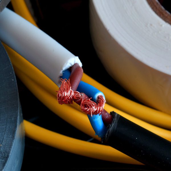
Copper has a long history of use in electric wiring since the invention of the electromagnet and telegraph. Copper wires are applied in a wide range of electronic equipment such as panels, meters, computers, business machines, and appliances thanks to its corrosion resistance, solderability, and performance at elevated temperatures up to 150°C. Approximately half of all mined copper is used for manufacturing electrical wire and cable conductors.
Copper wire surface quality is critical to application service performance and lifetime. Micro defects in wires may lead to excessive wear, crack initiation and propagation, decreased conductivity, and inadequate solderability. Proper surface treatment of copper wires removes surface defects generated during wire drawing improving corrosion, scratch, and wear resistance. Many aerospace applications with copper wires require controlled behavior to prevent unexpected equipment failure. Quantifiable and reliable measurements are needed to properly evaluate the wear and scratch resistance of the copper wire surface.
Measurement Objective
In this application we simulate a controlled wear process of different copper wire surface treatments. Scratch testing measures the load required to cause failure on the treated surface layer. This study showcases the Nanovea Tribometer and Mechanical Tester as ideal tools for evaluation and quality control of electric wires.
Test Procedure and Procedures
Coefficient of friction (COF) and wear resistance of two different surface treatments on copper wires (Wire A and Wire B) were evaluated by the Nanovea tribometer using a linear reciprocating wear module. An Al₂O₃ ball (6 mm diameter) is the counter material used in this application. The wear track was examined using Nanovea’s 3D non-contact profilometer. Test parameters are summarized in Table 1.
A smooth Al₂O₃ ball as a counter material was used as an example in this study. Any solid material with different shape and surface finish can be applied using a custom fixture to simulate the actual application situation.

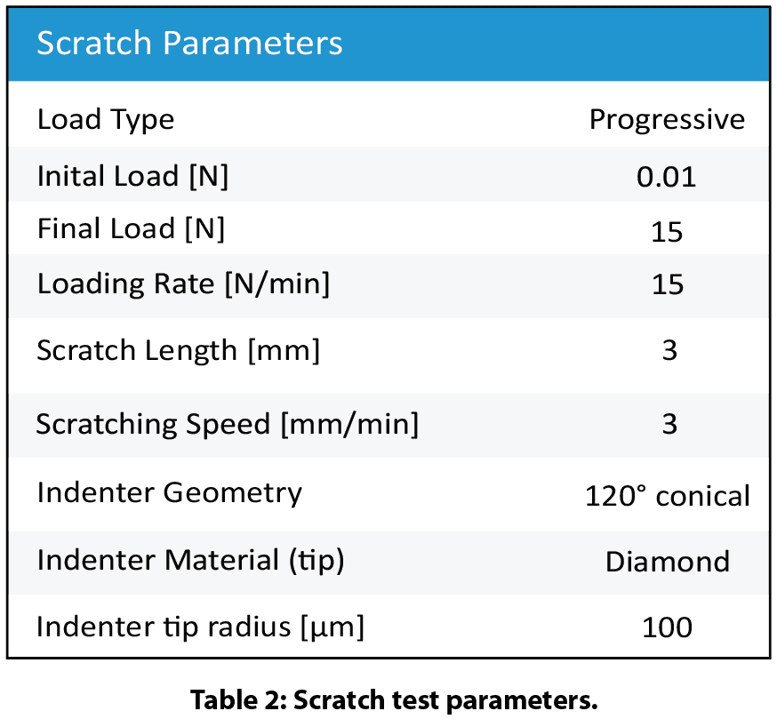
Nanovea’s mechanical tester equipped with a Rockwell C diamond stylus (100 μm radius) performed progressive load scratch tests on the coated wires using micro scratch mode. Scratch test parameters and tip geometry are shown in Table 2.
Results and Discussion
Wear of copper wire:
Figure 2 shows COF evolution of the copper wires during wear tests. Wire A shows a stable COF of ~0.4 throughout the wear test while wire B exhibits a COF of ~0.35 in the first 100 revolutions and progressively increases to ~0.4.
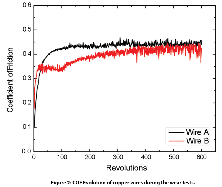
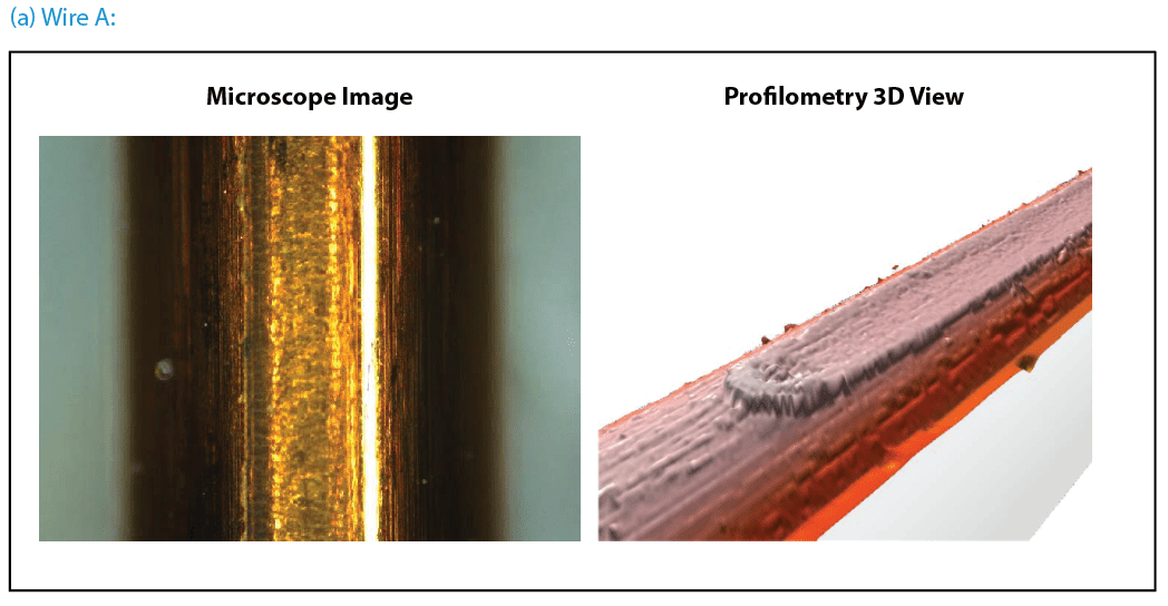
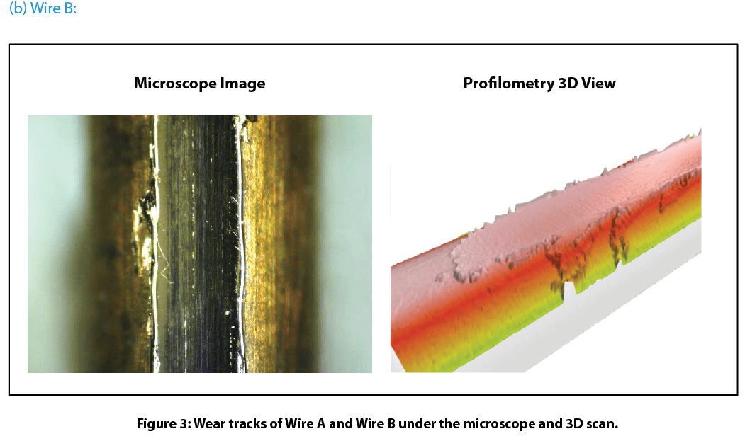
Figure 3 compares wear tracks of the copper wires after tests. Nanovea’s 3D non-contact profilometer offered superior analysis of the detailed morphology of wear tracks. It allows direct and accurate determination of the wear track volume by providing a fundamental understanding of the wear mechanism. Wire B’s surface has signi¬ficant wear track damage after a 600-revolution wear test. The profilometer 3D view shows the surface treated layer of Wire B removed completely which substantially accelerated the wear process. This left a flattened wear track on Wire B where copper substrate is exposed. This may result in significantly shortened lifespan of electrical equipment where Wire B is used. In comparison, Wire A exhibits relatively mild wear shown by a shallow wear track on the surface. The surface treated layer on Wire A did not remove like the layer on Wire B under the same conditions.
Scratch resistance of the copper wire surface:
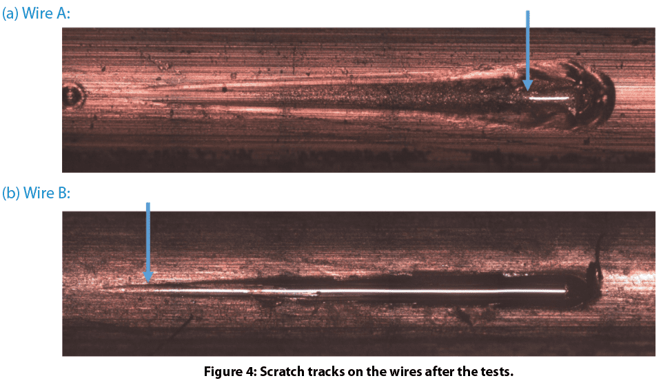
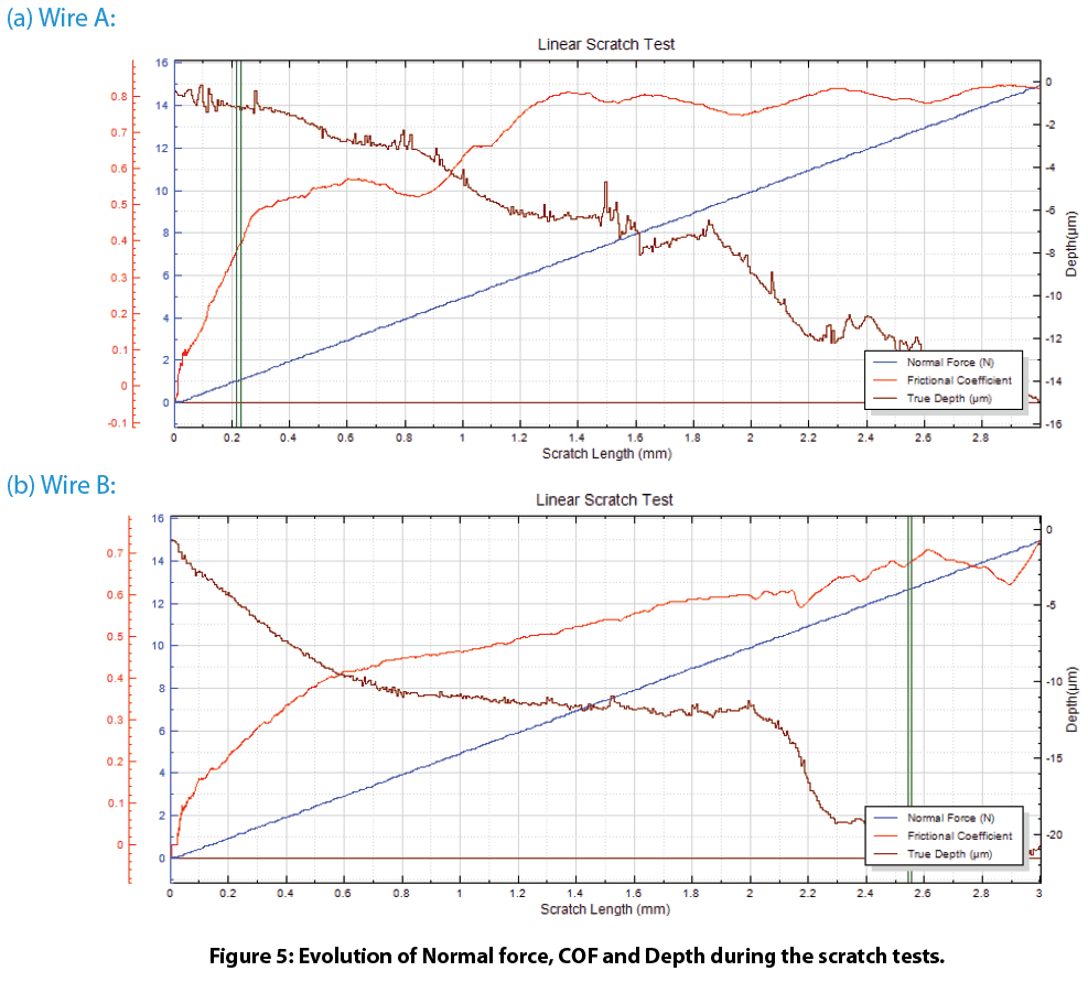
Figure 4 shows the scratch tracks on the wires after testing. The protective layer of Wire A exhibits very good scratch resistance. It delaminates at a load of ~12.6 N. In comparison, the protective layer of Wire B failed at a load of ~1.0 N. Such a significant difference in scratch resistance for these wires contributes to their wear performance, where Wire A possesses substantially enhanced wear resistance. The evolution of normal force, COF, and depth during the scratch tests shown in Fig. 5 provides more insight on coating failure during tests.
Conclusion

In this controlled study we showcased the Nanovea’s tribometer conducting quantitative evaluation of wear resistance for surface treated copper wires and Nanovea’s mechanical tester providing reliable assessment of copper wire scratch resistance. Wire surface treatment plays a critical role in the tribo-mechanical properties during their lifetime. Proper surface treatment on Wire A significantly enhanced wear and scratch resistance, critical in the performance and lifespan of electrical wires in rough environments.
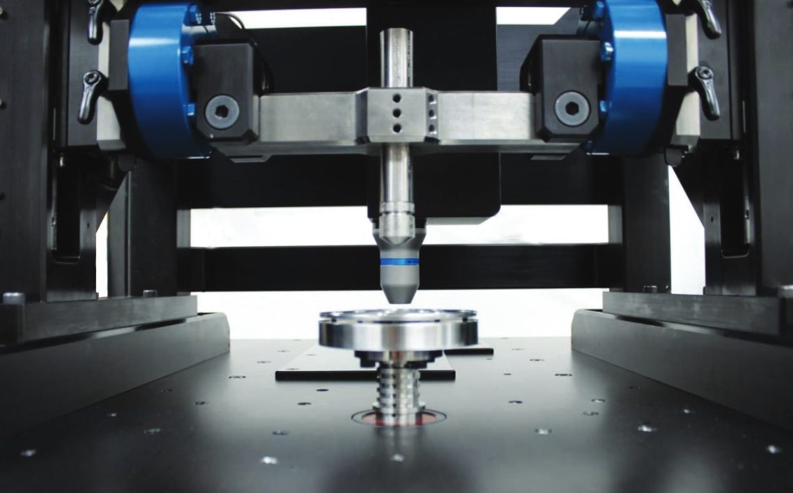
Nanovea’s tribometer offers precise and repeatable wear and friction testing using ISO and ASTM compliant rotative and linear modes, with optional high temperature wear, lubrication, and tribo-corrosion modules available in one pre-integrated system. Nanovea’s unmatched range is an ideal solution for determining the full range of tribological properties of thin or thick, soft or hard coatings, films, and substrates.
Dynamic Load Tribology
Introduction
Wear takes place in virtually every industrial sector and imposes costs of ~0.75% of the GDP1. Tribology research is vital in improving production efficiency, application performance, as well as conservation of material, energy, and the environment. Vibration and oscillation inevitably occur in a wide range of tribological applications. Excessive external vibration accelerates the wear process and reduces service performance which leads to catastrophic failures to the mechanical parts.
Conventional dead load tribometers apply normal loads by mass weights. Such a loading technique not only limits the loading options to a constant load, but it also creates intense uncontrolled vibrations at high loads and speeds leading to limited and inconsistent wear behavior assessments. A reliable evaluation of the effect of controlled oscillation on the wear behavior of materials is desirable for R&D and QC in different industrial applications.
Nanovea’s groundbreaking high load tribometer has a maximum load capacity of 2000 N with a dynamic load control system. The advanced pneumatic compressed air loading system enables users to evaluate the tribological behavior of a material under high normal loads with the advantage of damping undesired vibration created during the wear process. Therefore, the load is measured directly with no need for buffer springs used in older designs. A parallel electromagnet oscillating loading module applies well-controlled oscillation of desired amplitude up to 20 N and frequency up to 150 Hz.
Friction is measured with high accuracy directly from the side force applied to the upper holder. The displacement is monitored in situ, providing insight into the evolution of the wear behavior of the test samples. The wear test under controlled oscillation loading can also be performed in corrosion, high temperature, humidity, and lubrication environments to simulate the real work conditions for the tribological applications. An integrated high-speed non-contact profilometer automatically measures the wear track morphology and wear volume in a few seconds.
Measurement Objective
In this study, we showcase the capacity of the Nanovea T2000 Dynamic Load Tribometer in studying the tribological behavior of different coating and metal samples under controlled oscillation loading conditions.
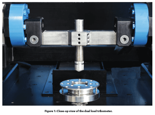
Test Procedure
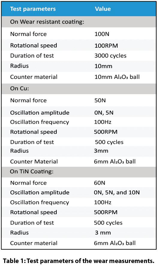
The tribological behavior, e.g. coefficient of friction, COF, and wear resistance of a 300 µm thick wear-resistant coating was assessed and compared by the Nanovea T2000 Tribometer with a conventional dead load tribometer using a pin on disk setup following ASTM G992.
Separate Cu and TiN coated samples against a 6 mm Al₂0₃ ball under controlled oscillation were evaluated by Dynamic Load Tribology Mode of the Nanovea T2000 Tribometer.
The test parameters are summarized in Table 1.
The integrated 3D profilometer equipped with a line sensor automatically scans the wear track after the tests, providing the most accurate wear volume measurement in seconds.
Results and Discussion
Pneumatic loading system vs. Dead load system
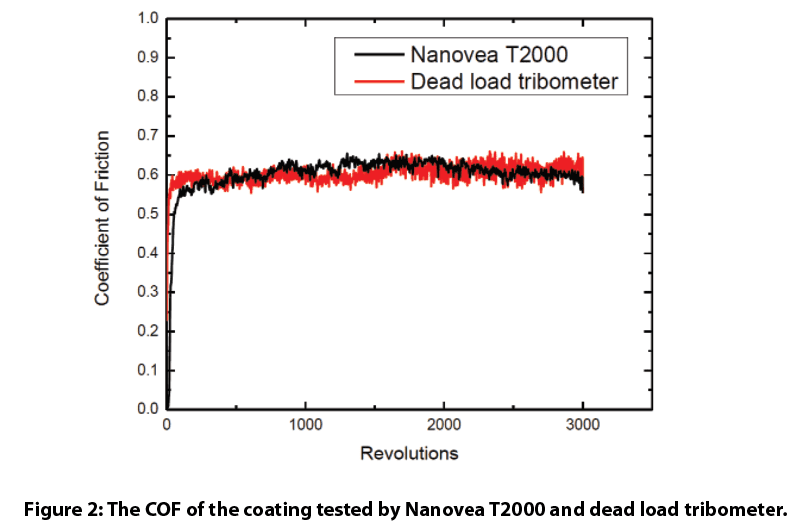
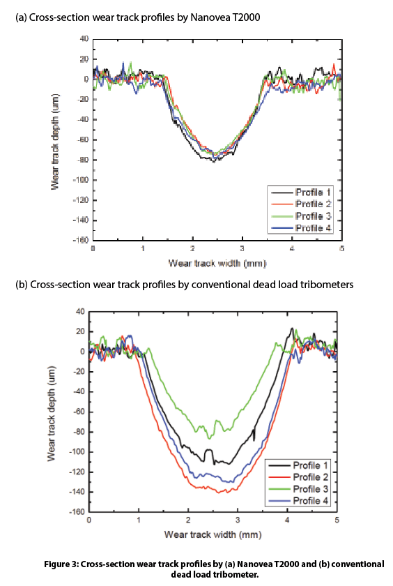
The tribological behavior of a wear-resistant coating using Nanovea T2000 Tribometer is compared to a conventional dead load (DL) tribometer. The evolution of the COF of the coating are shown in Fig. 2. We observe the coating exhibits a comparable COF value of ~0.6 during the wear test. However, the 20 cross-section profiles at different locations of the wear track in Fig. 3 indicate that the coating experienced much more severe wear under the dead load system.
Intense vibrations were generated by the wear process of the dead load system at high load and speed. The massive concentrated pressure at the contact face combined with a high sliding speed creates substantial weight and structure vibration leading to accelerated wear. The conventional dead load tribometer applies load using mass weights. This method is reliable at lower contact loads under mild wear conditions; however, under aggressive wear conditions at higher loads and speeds, the significant vibration causes the weights to bounce repeatedly, resulting in an uneven wear track causing unreliable tribological evaluation. The calculated wear rate is 8.0±2.4 x 10⁻⁴ mm3/N m, showing a high wear rate and large standard deviation.
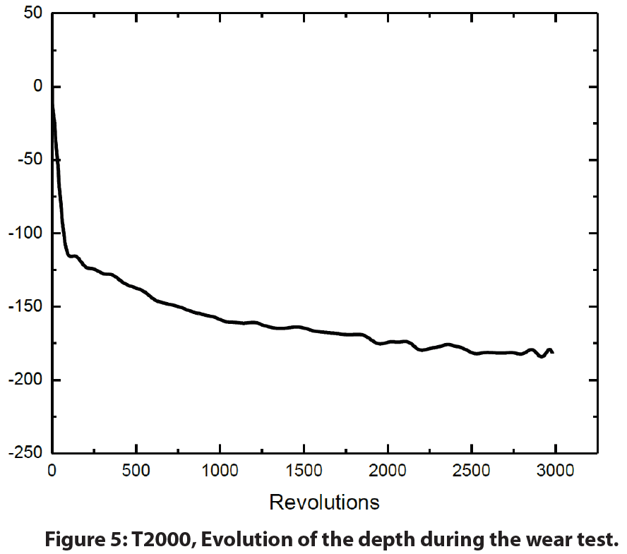
The Nanovea T2000 tribometer is designed with a dynamic control loading system to dampen the oscillations. It applies the normal load with compressed air which minimizes undesired vibration created during the wear process. In addition, active closed loop loading control ensures a constant load is applied throughout the wear test and the stylus follows the depth change of the wear track. A significantly more consistent wear track profile is measured as shown in Fig. 3a, resulting in a low wear rate of 3.4±0.5 x 10⁻⁴ mm3/N m.
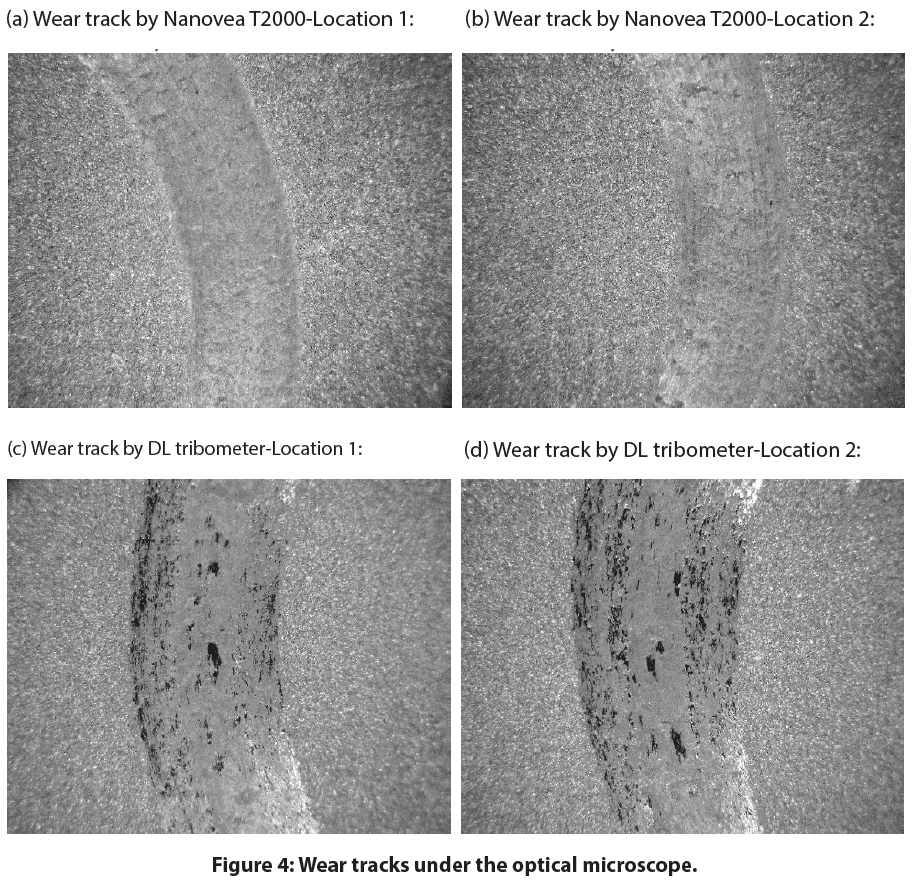
The wear track analysis shown in Fig. 4 confirms the wear test performed by the pneumatic compressed air loading system of the Nanovea T2000 Tribometer creates a smoother and more consistent wear track compared to the conventional dead load tribometer. In addition, the Nanovea T2000 tribometer measures stylus displacement during the wear process providing further insight into the progress of the wear behavior in situ.
Controlled Oscillation on Wear of the Cu sample
The parallel oscillating loading electromagnet module of the Nanovea T2000 Tribometer enables users to investigate the effect of controlled amplitude and frequency oscillations on the wear behavior of materials. The COF of the Cu samples is recorded in situ as shown in Fig. 6. The Cu sample exhibits a constant COF of ~0.3 during the first 330-revolution measurement, signifying the formation of a stable contact at the interface and relatively smooth wear track. As the wear test continues, the variation of the COF indicates a change in the wear mechanism. In comparison, the wear tests under a 5 N amplitude-controlled oscillation at 50 N exhibits a different wear behavior: the COF increases promptly at the beginning of the wear process, and shows significant variation throughout the wear test. Such behavior of COF indicates that the imposed oscillation in the normal load plays a role in the unstable sliding state at the contact.
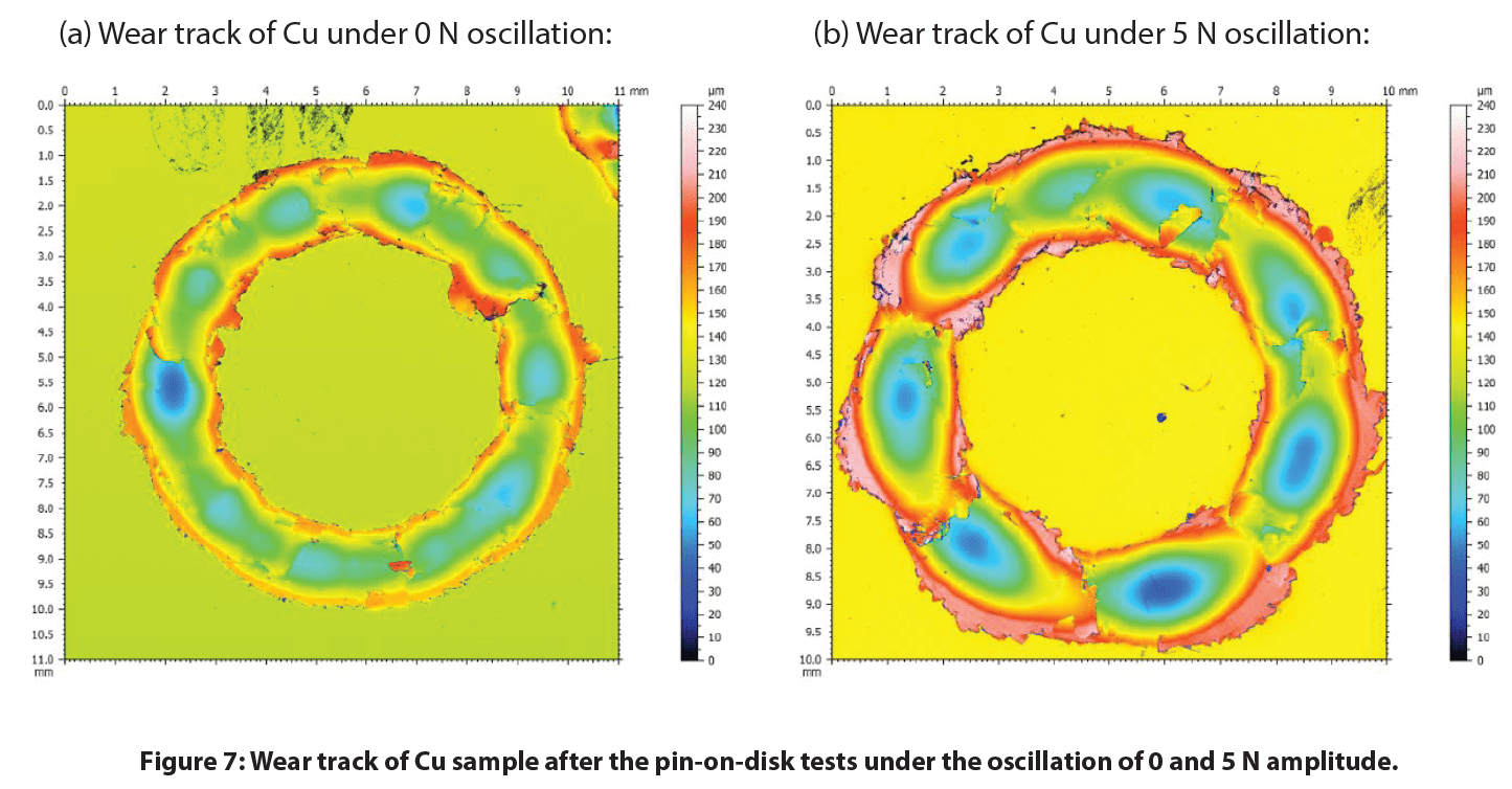
Fig. 7 compares the wear track morphology measured by the integrated non-contact optical profilometer. It can be observed that the Cu sample under a controlled oscillation amplitude of 5 N exhibits a much larger wear track with a volume of 1.35 x 109 µm3, compared to 5.03 x 108 µm3 under no imposed oscillation. The controlled oscillation significantly accelerates the wear rate by a factor of ~2.7, showing the critical effect of oscillation on wear behavior.

Controlled Oscillation on Wear of the TiN Coating
The COF and wear tracks of the TiN coating sample are shown in Fig. 8. The TiN coating exhibits significantly different wear behaviors under oscillation as indicated by the evolution of COF during the tests. The TiN coating shows a constant COF of ~0.3 following the run-in period at the beginning of the wear test, due to the stable sliding contact at the interface between the TiN coating and the Al₂O₃ ball. However, when the TiN coating starts to fail, the Al₂O₃ ball penetrates through the coating and slides against the fresh steel substrate underneath. A significant amount of hard TiN coating debris is generated in the wear track at the same time, turning a stable two-body sliding wear into three-body abrasion wear. Such a change of the material couple characteristics leads to the increased variations in the evolution of COF. The imposed 5 N and 10 N oscillation accelerates the TiN coating failure from ~400 revolutions to below 100 revolutions. The larger wear tracks on the TiN coating samples after the wear tests under the controlled oscillation is in agreement with such a change in COF.

Conclusion
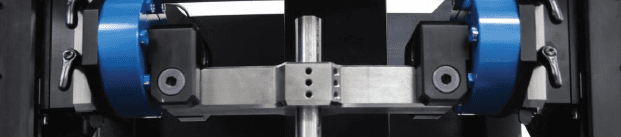
The advanced pneumatic loading system of the Nanovea T2000 Tribometer possesses an intrinsic advantage as a naturally quick vibration damper compared to traditional dead load systems. This technological advantage of pneumatic systems is true compared to load-controlled systems that use a combination of servo motors and springs to apply the load. The technology ensures reliable and better-controlled wear evaluation at high loads as demonstrated in this study. In addition, the active closed loop loading system can change the normal load to a desired value during wear tests to simulate real-life applications seen in brake systems.
Instead of having influence from uncontrolled vibration conditions during tests, we have shown the Nanovea T2000 Dynamic-Load Tribometer enables users to quantitatively assess the tribological behaviors of materials under different controlled oscillation conditions. Vibrations play a significant role in the wear behavior of metal and ceramic coating samples.
The parallel electromagnet oscillating loading module provides precisely controlled oscillations at set amplitudes and frequencies, allowing users to simulate the wear process under real-life conditions when environmental vibrations are often an important factor. In the presence of imposed oscillations during wear, both the Cu and the TiN coating samples exhibit substantially increased wear rate. The evolution of the coefficient of friction and stylus displacement measured in situ are important indicators for the performance of the material during the tribological applications. The integrated 3D non-contact profilometer offers a tool to precisely measure the wear volume and analyze the detailed morphology of the wear tracks in seconds, providing more insight into the fundamental understanding of wear mechanism.
The T2000 is equipped with a self-tuned, high-quality, and high torque motor with a 20-bit internal speed and a 16-bit external position encoder. It enables the tribometer to provide an unmatched range of rotational speeds from 0.01 to 5000 rpm that can change in stepwise jumps or at continuous rates. Contrary to systems that use a bottom located torque sensor, the Nanovea Tribometer uses a top located high-precision load cell to accurately and separately measure friction forces.
Nanovea Tribometers offers precise and repeatable wear and friction testing using ISO and ASTM compliant rotative and linear modes (including 4ball, thrust washer, and block on ring tests), with optional high-temperature wear, lubrication and tribo-corrosion modules available in one pre-integrated system. Nanovea T2000’s unmatched range is an ideal solution for determining the full range of tribological properties of thin or thick, soft or hard coatings, films, and substrates.

Paint Orange Peel Texture Analysis using 3D Profilometry
Introduction
The size and frequency of surface structures on substrates affect the quality of gloss coatings. Paint orange peel texture, named after its appearance, can develop from substrate influence and paint application technique. Texture problems are commonly quantified by waviness, wavelength, and the visual effect they have on gloss coatings. The smallest textures result in gloss reduction while larger textures result in visible ripples on the coated surface. Understanding the development of these textures and its relation to substrates and techniques are critical to quality control.
Importance of Profilometry for Texture Measurement
Unlike traditional 2D instruments used to measure gloss texture, 3D non-contact measurement quickly provides a 3D image used to understand surface characteristics with the added ability to quickly investigate areas of interest. Without speed and 3D review, a quality control environment would solely rely on 2D information that gives little predictability of the entire surface. Understanding textures in 3D allows for the best selection of processing and control measures. Assuring quality control of such parameters heavily relies on quantifiable, reproducible, and reliable inspection. Nanovea 3D Non-Contact Profilometers utilize chromatic confocal technology to have the unique capability to measure the steep angles found during fast measurement. Nanovea Profilometers succeed where other techniques fail to provide reliable data due to probe contact, surface variation, angle, or reflectivity.
Measurement Objective
In this application, the Nanovea HS2000L measures the paint orange peel texture of a gloss paint. There are endless surface parameters automatically calculated from the 3D surface scan. Here we analyze a scanned 3D surface by quantifying the characteristics of the paint orange peel texture.
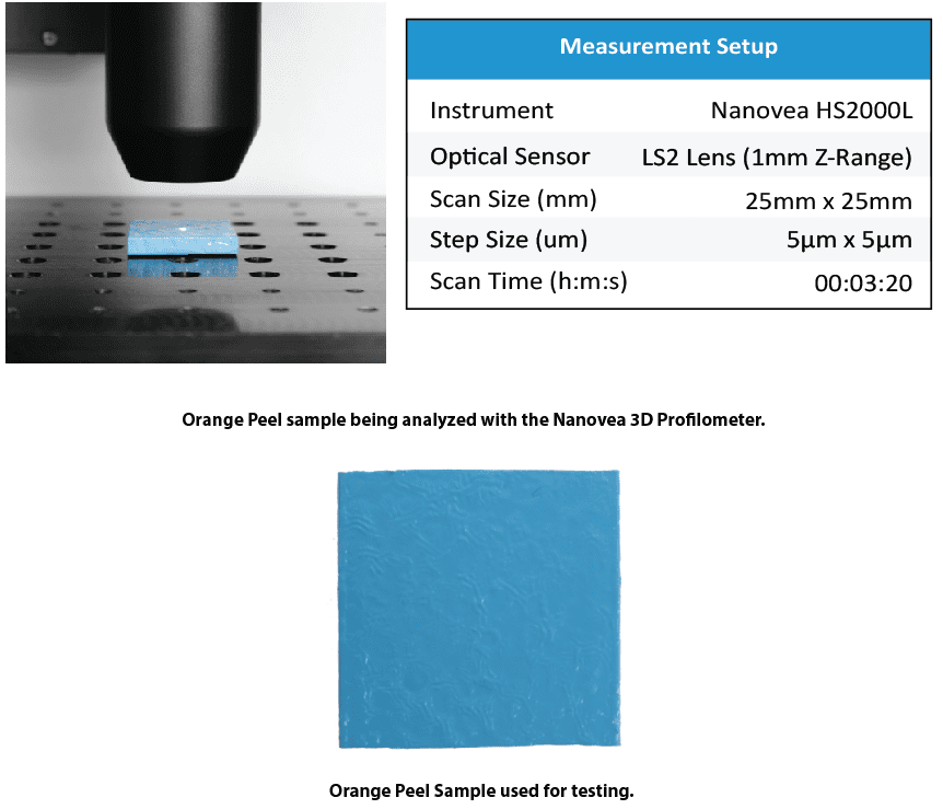
Results and Discussion

The Nanovea HS2000L quantified isotropy and height parameters of the orange peel paint. The orange peel texture quantified the random pattern direction with 94.4% isotropy. Height parameters quantify the texture with a 24.84µm height difference.

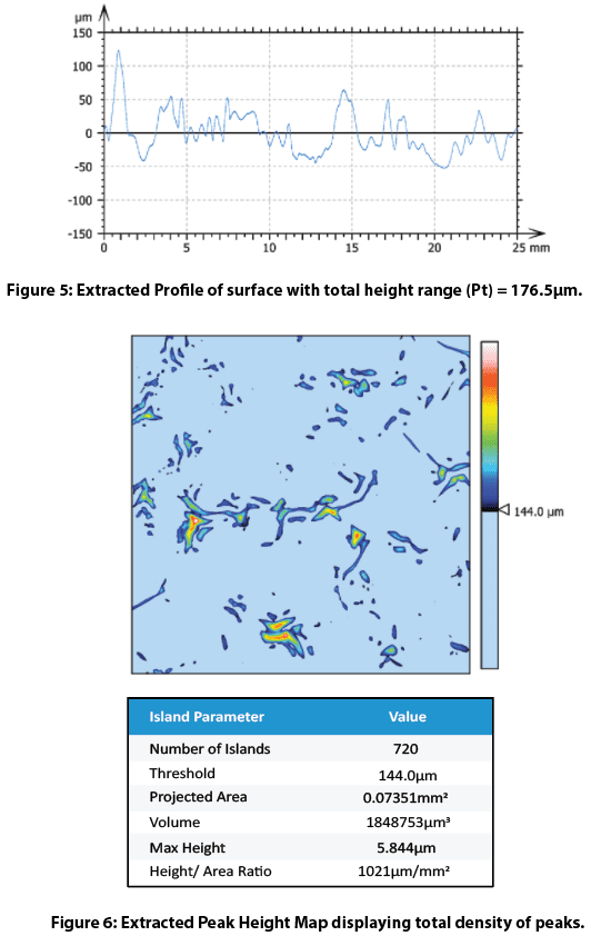
The bearing ratio curve in Figure 4 is a graphical representation of the depth distribution. This is an interactive feature within the software that allows the user to view distributions and percentages at varying depths. An extracted profile in Figure 5 gives useful roughness values for the orange peel texture. Peak extraction above a 144 micron threshold shows the orange peel texture. These parameters are easily adjusted to other areas or parameters of interest.
Conclusion
In this application, the Nanovea HS2000L 3D Non-Contact Profilometer precisely characterizes both topography and nanometer details of the paint orange peel texture on a gloss coating. Areas of interest from 3D surface measurements are quickly identified and analyzed with many useful measurements (Dimension, Roughness Finish Texture, Shape Form Topography, Flatness Warpage Planarity, Volume Area, Step-Height, etc.). Quickly chosen 2D cross-sections provide a complete set of surface measurement resources on gloss texture. Special areas of interest can be further analyzed with an integrated AFM module. Nanovea 3D Profilometer’s speed ranges from <1 mm/s to 500 mm/s for suitability in research applications to the needs of high-speed inspection. Nanovea 3D Profilometers have a wide range of configurations to suit your application.

3D Surface Analysis of a Penny with Non-contact Profilometry
Importance of Non-contact Profilometry for Coins
Currency is highly valued in modern society because it is traded for goods and services. Coin and paper bill currency circulates around the hands of many people. Constant transfer of physical currency creates surface deformation. Nanovea’s 3D Profilometer scans the topography of coins minted in different years to investigate surface differences.
Coin features are easily recognizable to the general public since they are common objects. A penny is ideal for introducing the strength of Nanovea’s Advanced Surface Analysis Software: Mountains 3D. Surface data collected with our 3D Profilometer allows for high level analyses on complex geometry with surface subtraction and 2D contour extraction. Surface subtraction with a controlled mask, stamp, or mold compares the quality of manufacturing processes while contour extraction identifies tolerances with dimensional analysis. Nanovea’s 3D Profilometer and Mountains 3D software investigates the submicron topography of seemingly simple objects, like pennies.
Measurement Objective
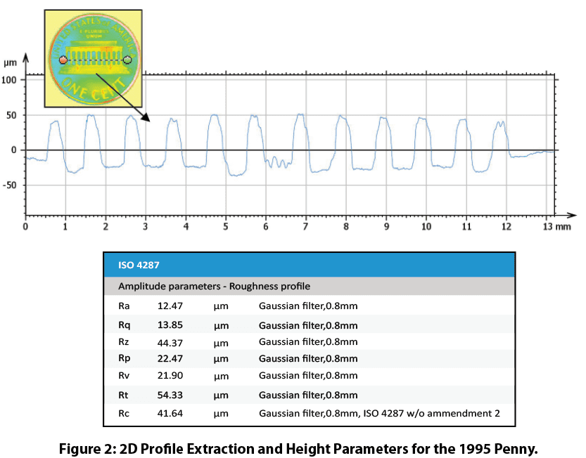
The full upper surface of five pennies were scanned using Nanovea’s High-Speed Line Sensor. The inner and outer radius of each penny was measured using Mountains Advanced Analysis Software. An extraction from each penny surface at an area of interest with direct surface subtraction quantified surface deformation.

Results and Discussion
3D Surface
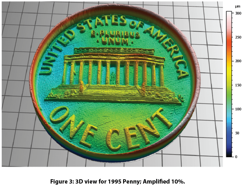
The Nanovea HS2000 profilometer took only 24 seconds to scan 4 million points in a 20mm x 20mm area with a 10um x 10um step size to acquire the surface of a penny. Below is a height map and 3D visualization of the scan. The 3D view shows the High-Speed sensor’s ability to pick up small details unperceivable to the eye. Many small scratches are visible across the surface of the penny. Texture and roughness of the coin seen in the 3D view are investigated.

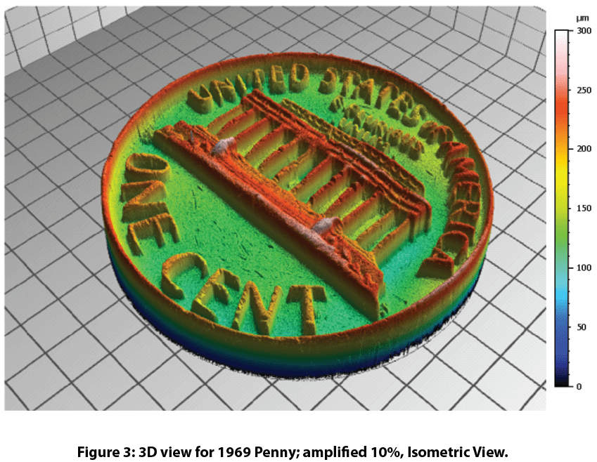
Dimensional Analysis
The contours of the penny were extracted and dimensional analysis obtained inner and outer diameters of the edge feature. The outer radius averaged 9.500 mm ± 0.024 while the inner radius averaged 8.960 mm ± 0.032. Additional dimensional analyses Mountains 3D can do on 2D and 3D data sources are distance measurements, step height, planarity, and angle calculations.
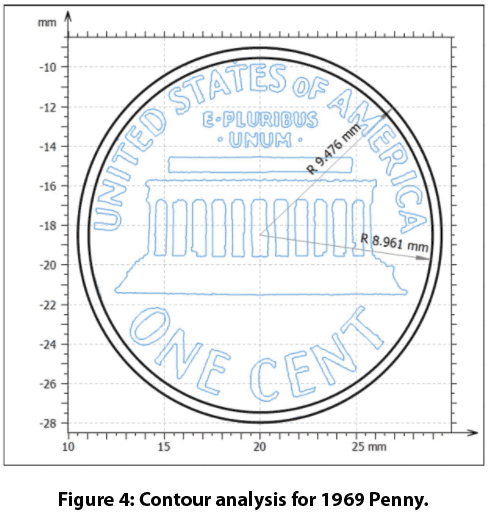

Surface Subtraction
Figure 5 shows the area of interest for the surface subtraction analysis. The 2007 penny was used as the reference surface for the four older pennies. Surface subtraction from the 2007 penny surface shows differences between pennies with holes/peaks. Total surface volume difference is obtained from adding volumes of the holes/peaks. The RMS error refers to how closely penny surfaces agree with each other.
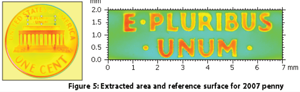

Conclusion

Nanovea’s High-Speed HS2000L scanned five pennies minted in different years. Mountains 3D software compared surfaces of each coin using contour extraction, dimensional analysis, and surface subtraction. The analysis clearly defines the inner and outer radius between the pennies while directly comparing surface feature differences. With Nanovea’s 3D profilometer’s ability to measure any surfaces with nanometer-level resolution, combined with Mountains 3D analysis capabilities, the possible Research and Quality Control applications are endless.
Dimensional and Surface Finish of Polymeric Tubes
Importance of Dimensional and Surface Analysis of Polymeric Tubes
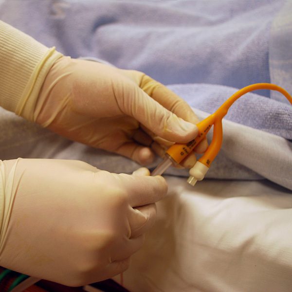
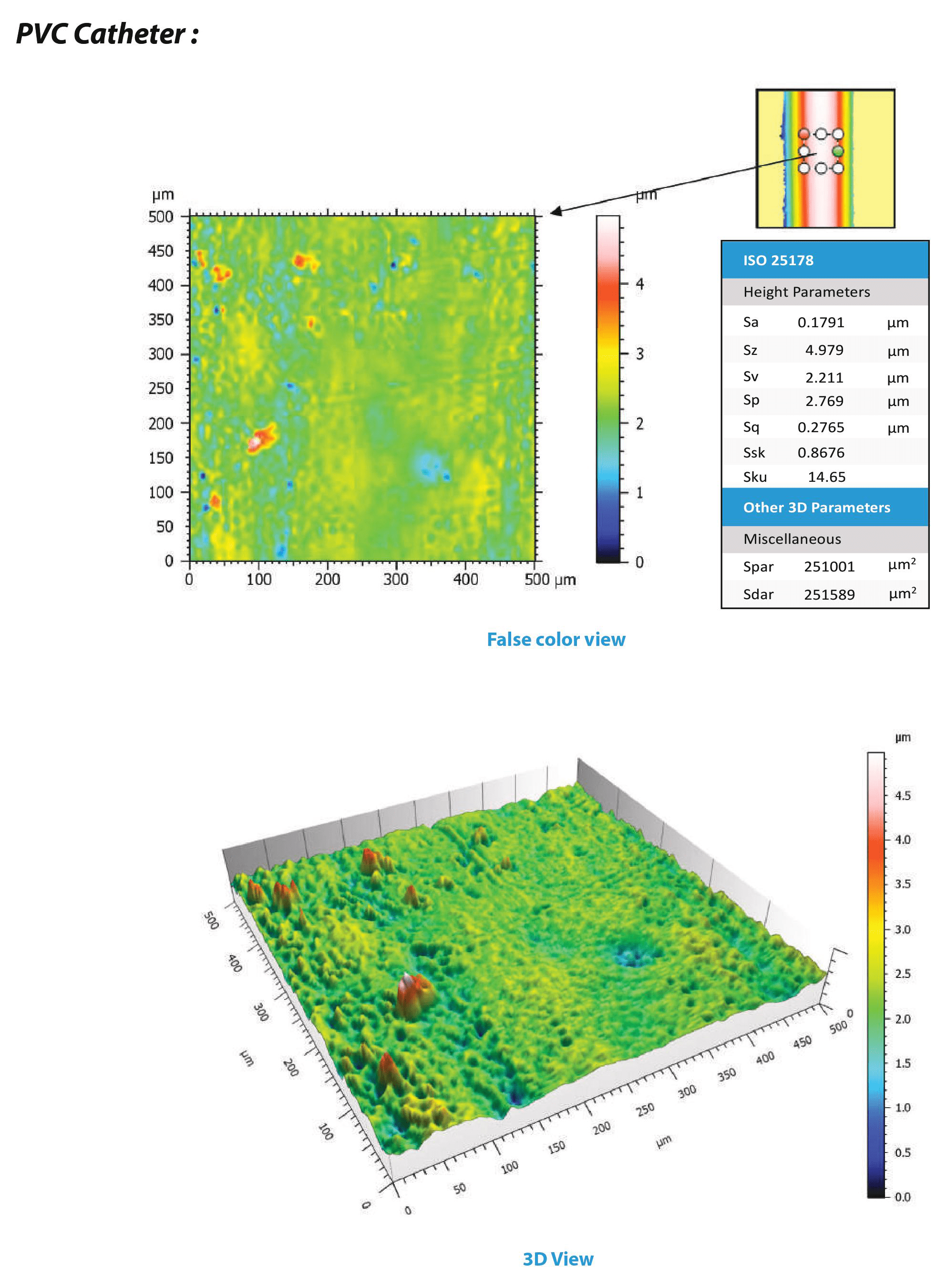
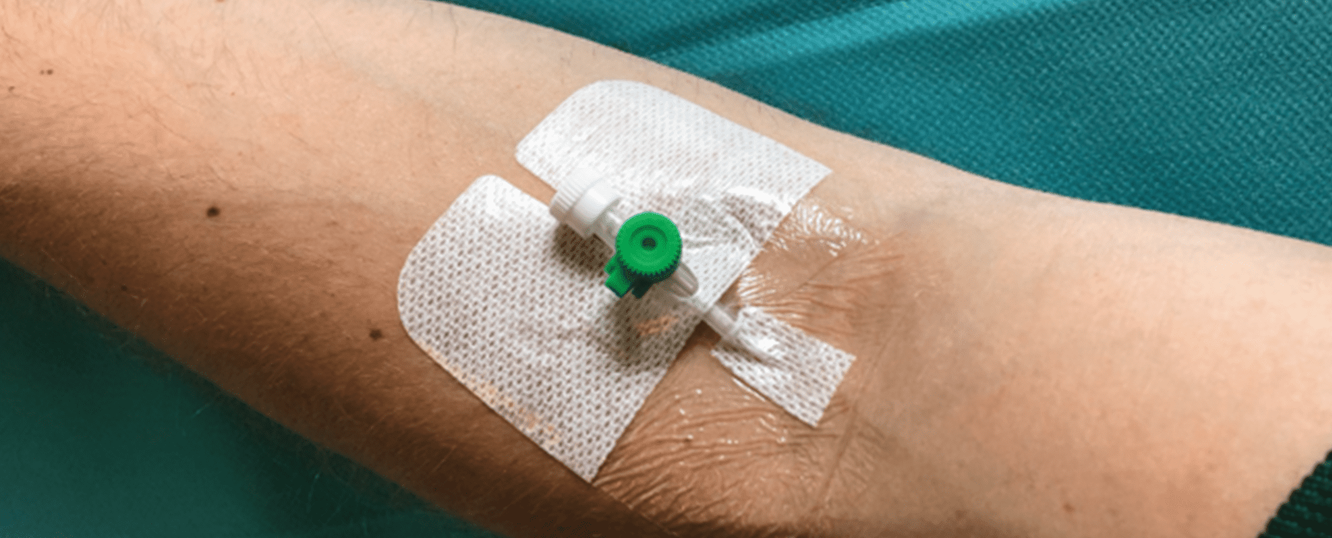
Tubes made from polymeric material are commonly used in many industries ranging from automotive, medical, electrical, and many other categories. In this study, medical catheters made of different polymeric materials were studied using the Nanovea 3D Non-Contact Profilometer to measure surface roughness, morphology, and dimensions. Surface roughness is crucial for catheters as many problems with catheters, including infection, physical trauma, and inflammation can be linked with the catheter surface. Mechanical properties, such as coefficient of friction, can also be studied by observing surface properties. These quantifiable data can be obtained to ensure the catheter can be used for medical applications.
Compared to optical microscopy and electron microscopy, 3D Non-Contact Profilometry using axial chromatism is highly preferable for characterizing catheter surfaces due to its ability to measure angles/curvature, ability to measure material surfaces despite transparency or reflectivity, minimal sample preparation, and non-invasive nature. Unlike conventional optical microscopy, the height of the surface can be obtained and used for computational analysis; e.g. finding dimensions and removing form to find surface roughness. Having little sample preparation, in contrast to electron microscopy, and non-contact nature also allows for quick data collection without fearing contamination and error from sample preparation.
Measurement Objective
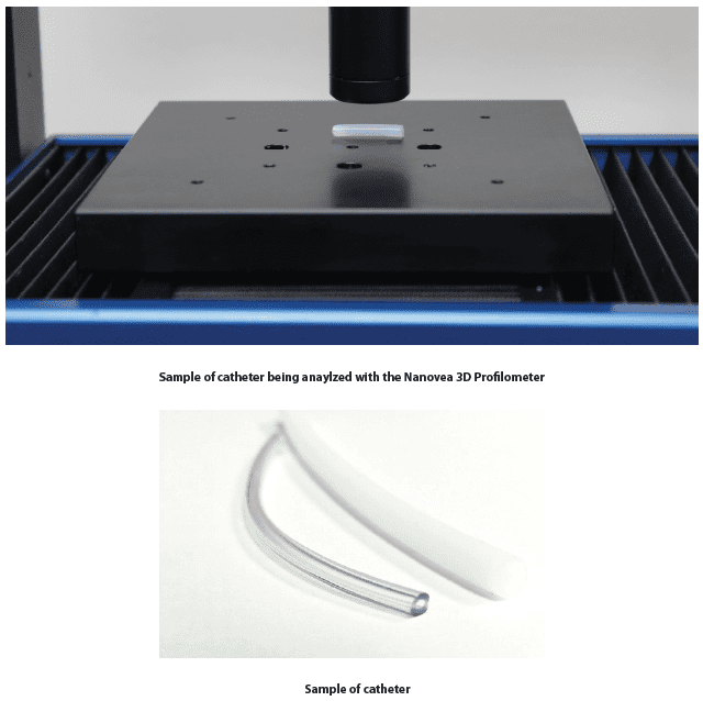
In this application, the Nanovea 3D Non-Contact Profilometer is used to scan the surface of two catheters: one made of TPE (Thermoplastic Elastomer) and the other made of PVC (Polyvinyl Chloride). The morphology, radial dimension, and height parameters of the two catheters will be obtained and compared.
Results and Discussion
3D Surface
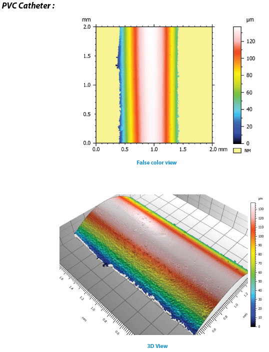
Despite the curvature on polymeric tubes, the Nanovea 3D Non-contact profilometer can scan the surface of the catheters. From the scan done, a 3D image can be obtained for quick, direct visual inspection of the surface.

2D Dimensional Analysis
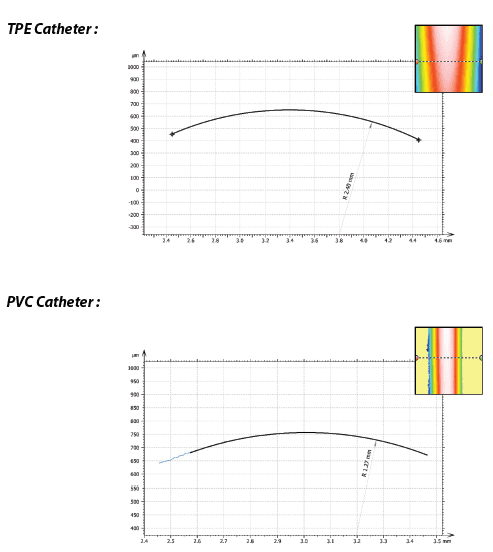
The outer radial dimension was obtained by extracting a profile from the original scan and fitting an arc to the profile. This shows the ability of the 3D Non-contact profilometer in conducting quick dimensional analysis for quality control applications. Multiple profiles can easily be obtained along the catheter’s length as well.
Surface Analysis Roughness
The outer radial dimension was obtained by extracting a profile from the original scan and fitting an arc to the profile. This shows the ability of the 3D Non-contact profilometer in conducting quick dimensional analysis for quality control applications. Multiple profiles can easily be obtained along the catheter’s length as well.
Conclusion
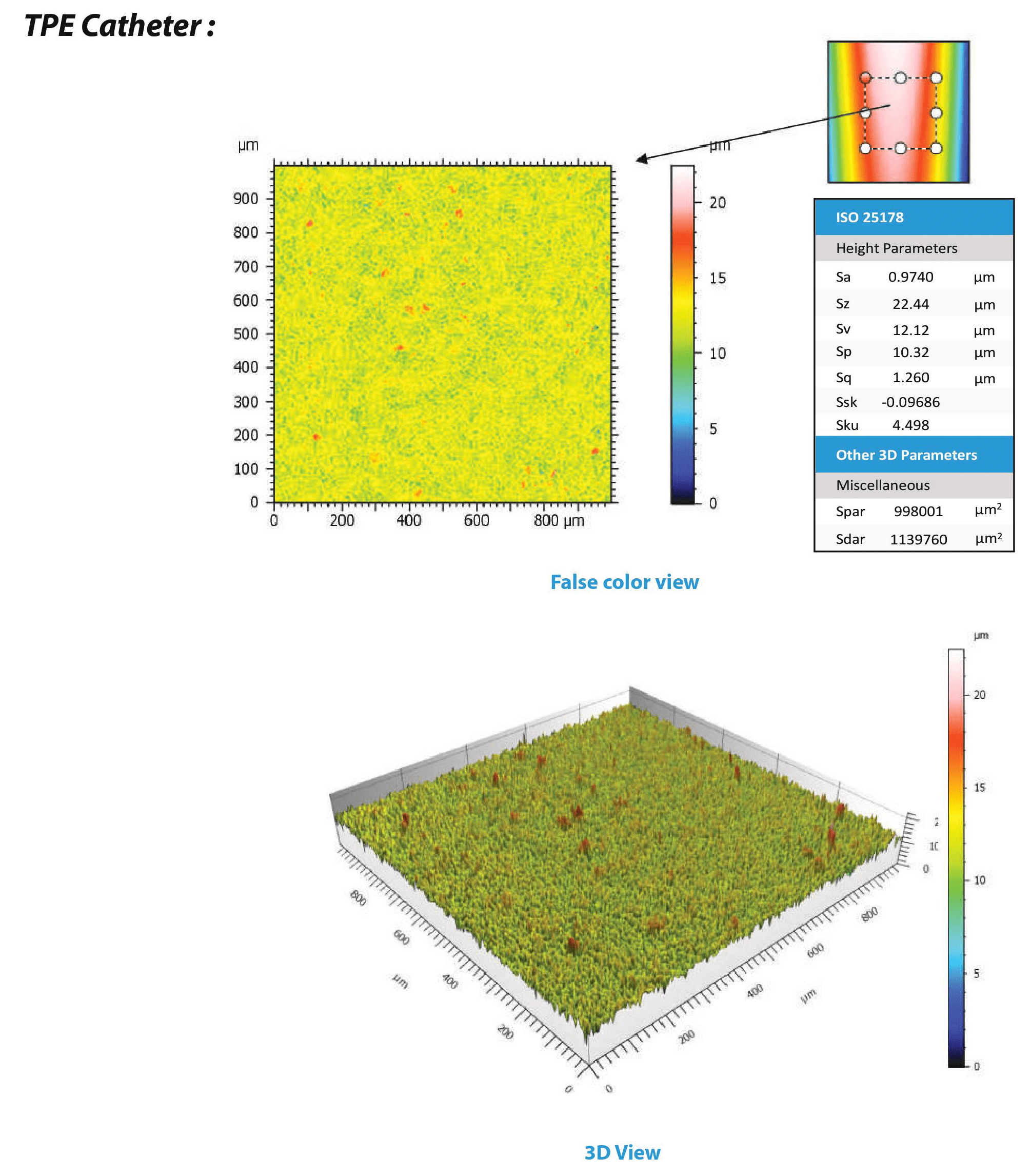
In this application, we have shown how the Nanovea 3D Non-contact profilometer can be used to characterize polymeric tubes. Specifically, surface metrology, radial dimensions, and surface roughness were obtained for medical catheters. The outer radius of the TPE catheter was found to be 2.40mm while the PVC catheter was 1.27mm. The surface of the TPE catheter was found to be rougher than the PVC catheter. The Sa of TPE was 0.9740µm compared to 0.1791µm of PVC. While medical catheters were used for this application, 3D Non-Contact Profilometry can be applied to a large variety of surfaces as well. Obtainable data and calculations are not limited to what is shown.
Tribology of Polymers
Introduction
Polymers have been used extensively in a wide variety of applications and have become an indispensable part of everyday life. Natural polymers such as amber, silk, and natural rubber have played an essential role in human history. The fabrication process of synthetic polymers can be optimized to achieve unique physical properties such as toughness, viscoelasticity, self-lubrication, and many others.
Importance of Wear and Friction of Polymers
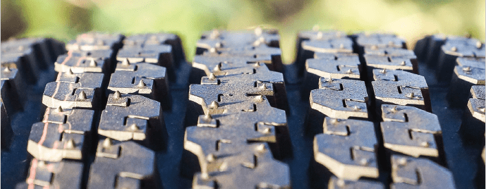
Polymers are commonly used for tribological applications, such as tires, bearings, and conveyor belts.
Different wear mechanisms occur depending on the mechanical properties of the polymer, the contact conditions, and the properties of the debris or transfer film formed during the wear process. To ensure that the polymers possess sufficient wear resistance under the service conditions, reliable and quantifiable tribological evaluation is necessary. Tribological evaluation allows us to quantitatively compare the wear behaviors of different polymers in a controlled and monitored manner to select the material candidate for the target application.
The Nanovea Tribometer offers repeatable wear and friction testing using ISO and ASTM compliant rotative and linear modes, with optional high-temperature wear and lubrication modules available in one pre-integrated system. This unmatched range allows users to simulate the different work environments of the polymers including concentrated stress, wear, and high temperature, etc.
MEASUREMENT OBJECTIVE
In this study, we showcased that the Nanovea Tribometer is an ideal tool for comparing the friction and wear resistance of different polymers in a well-controlled and quantitative manner.
TEST PROCEDURE
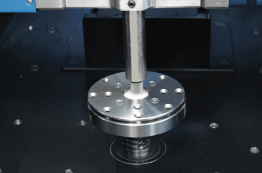
The coefficient of friction (COF) and the wear resistance of different common polymers were evaluated by the Nanovea Tribometer. An Al2O3 ball was used as the counter material (pin, static sample). The wear tracks on the polymers (dynamic rotating samples) were measured using a non-contact 3D profilometer and optical microscope after the tests concluded. It should be noted that a non-contact endoscopic sensor can be used to measure the depth the pin penetrates the dynamic sample during a wear test as an option. The test parameters are summarized in Table 1. The wear rate, K, was evaluated using the formula K=Vl(Fxs), where V is the worn volume, F is the normal load, and s is the sliding distance.
Please note that Al2O3 balls were used as the counter material in this study. Any solid material can be substituted to more closely simulate the performance of two specimens under actual application conditions.
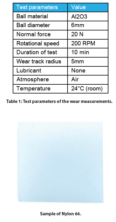
RESULTS AND DISCUSSION
Wear rate is a vital factor for determining the service lifetime of the materials, while the friction plays a critical role during the tribological applications. Figure 2 compares the evolution of the COF for different polymers against the Al2O3 ball during the wear tests. COF works as an indicator of when failures occur and the wear process enters a new stage. Among the tested polymers, HDPE maintains the lowest constant COF of ~0.15 throughout the wear test. The smooth COF implies that a stable tribo-contact is formed.
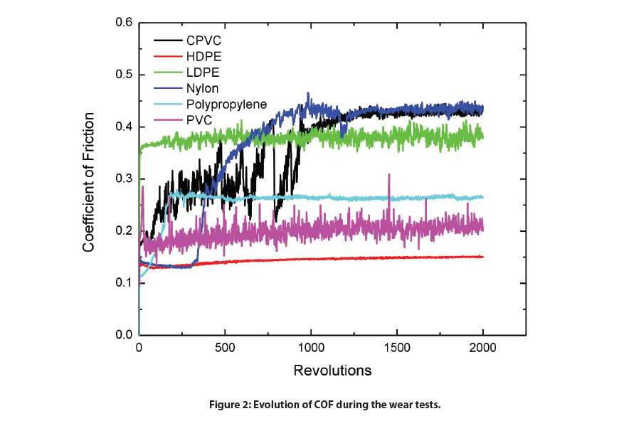
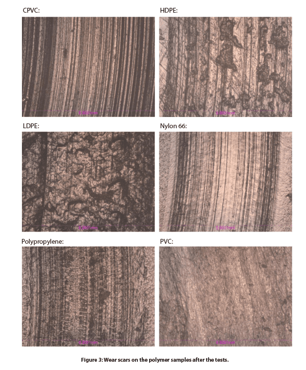
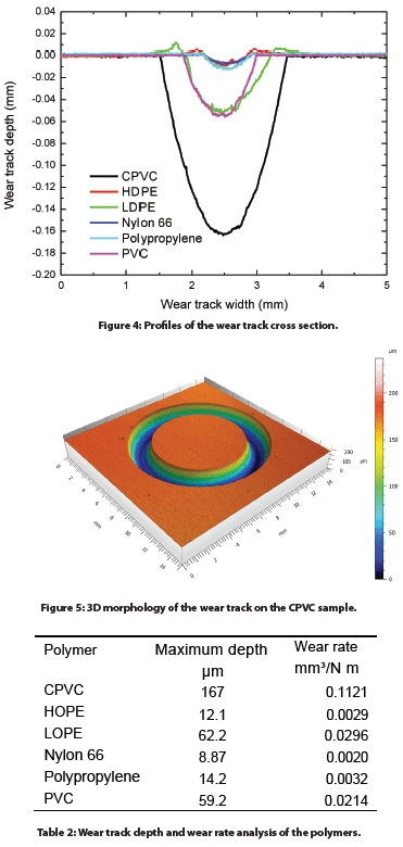
Figure 3 and Figure 4 compare the wear tracks of the polymer samples after the test is measured by the optical microscope. The In-situ non-contact 3D profilometer precisely determines the wear volume of the polymer samples, making it possible to accurately calculate wear rates of 0.0029, 0.0020, and 0.0032m3/N m, respectively. In comparison, the CPVC sample shows the highest wear rate of 0.1121m3/N m. Deep parallel wear scars are present in the wear track of CPVC.
CONCLUSION
The wear resistance of the polymers plays a vital role in their service performance. In this study, we showcased that the Nanovea Tribometer evaluates the coefficient of friction and wear rate of different polymers in a
well-controlled and quantitative manner. HDPE shows the lowest COF of ~0.15 among the tested polymers. HDPE, Nylon 66, and Polypropylene samples possess low wear rates of 0.0029, 0.0020 and 0.0032 m3/N m, respectively. The combination of low friction and great wear resistance makes HDPE a good candidate for polymer tribological applications.
The In-situ non-contact 3D profilometer enables precise wear volume measurement and offers a tool to analyze the detailed morphology of the wear tracks, providing more insight into the fundamental understanding of wear mechanisms

Honeycomb Panel Surface Finish with 3D Profilometry
INTRODUCTION
Roughness, porosity, and texture of the honeycomb panel surface are critical to quantify for the final panel design. These surface qualities can directly correlate to the aesthetics and functional characteristics of the panel surface. A better understanding of the surface texture and porosity can help optimize the panel surface processing and manufacturability. A quantitative, precise, and reliable surface measurement of the honeycomb panel is needed to control surface parameters for application and painting requirements. The Nanovea 3D Non-Contact sensors utilize unique chromatic confocal technology capable of precisely measuring these panel surfaces.
MEASUREMENT OBJECTIVE
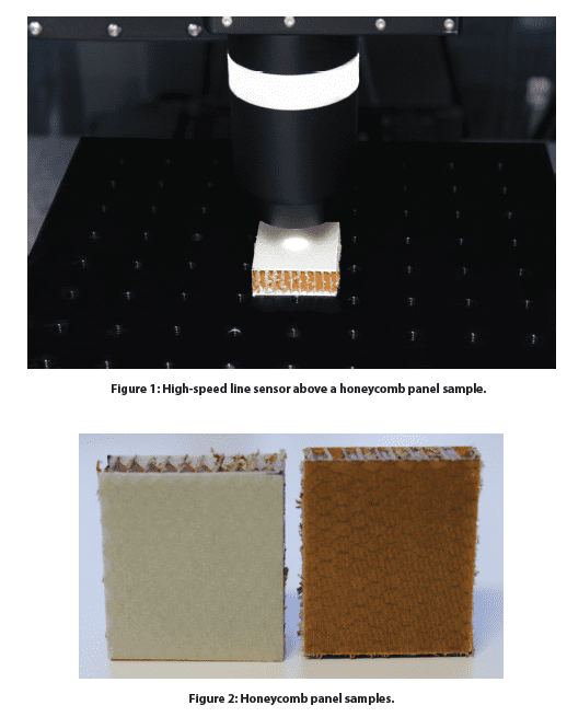
In this study, the Nanovea HS2000 platform equipped with a high-speed Line Sensor was used to measure and compare two honeycomb panels with different surface finishes. We showcase the Nanovea non-contact profilometer’s ability to provide fast and precise 3D profiling measurements and comprehensive in-depth analysis of the surface finish.
RESULTS AND DISCUSSION
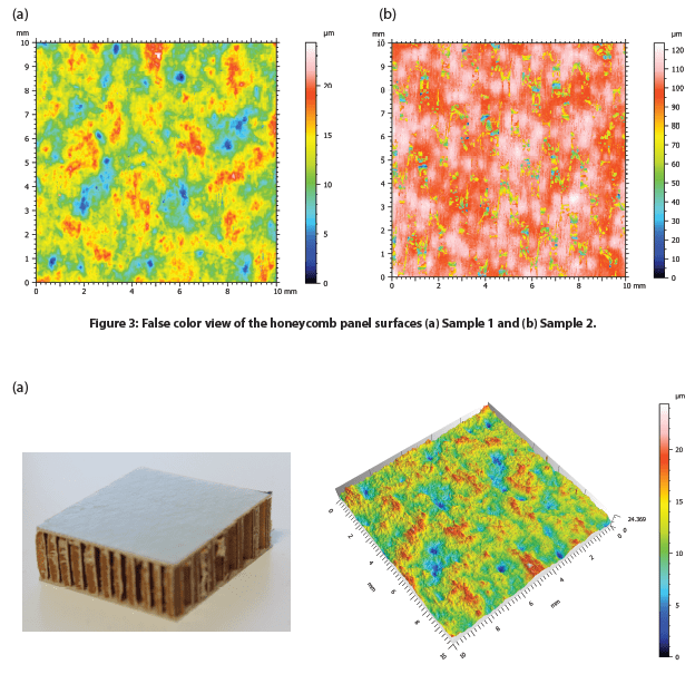
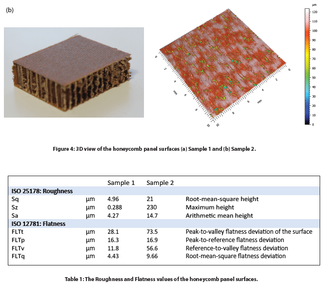
The surface of two honeycomb panel samples with varied surface finishes, namely Sample 1 and Sample 2, were measured. The false color and 3D view of the Samples 1 and 2 surfaces are shown in Figure 3 and Figure 4, respectively. The roughness and flatness values were calculated by advanced analysis software and are compared in Table 1. Sample 2 exhibits a more porous surface compared to Sample 1. As a result, Sample 2 possesses a higher roughness Sa of 14.7 µm, compared to an Sa value of 4.27 µm for Sample 1.
The 2D profiles of the honeycomb panel surfaces were compared in Figure 5, allowing users to have a visual comparison of the height change at different locations of the sample surface. We can observe that Sample 1 has a height variation of ~25 µm between the highest peak and lowest valley location. On the other hand, Sample 2 shows several deep pores across the 2D profile. The advanced analysis software has the ability to automatically locate and measure the depth of six relatively deep pores as shown in the table of Figure 4.b Sample 2. The deepest pore amongst the six possesses a maximum depth of nearly 90 µm (Step 4).
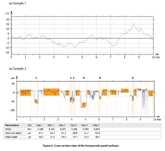
To further investigate the pore size and distribution of Sample 2, porosity evaluation was performed and discussed in the following section. The sliced view is displayed in Figure 5 and the results are summarized in Table 2. We can observe that the pores, marked in blue color in Figure 5, have a relatively homogeneous distribution on the sample surface. The projected area of the pores constitutes 18.9% of the whole sample surface. The volume per mm² of the total pores is ~0.06 mm³. The pores have an average depth of 42.2 µm, and the maximum depth is 108.1 µm.

CONCLUSION

In this application, we have showcased that the Nanovea HS2000 platform equipped with a high-speed Line Sensor is an ideal tool for analyzing and comparing the surface finish of honeycomb panel samples in a fast and accurate manner. The high-resolution profilometry scans paired with an advanced analysis software allow for a comprehensive and quantitative evaluation of the surface finish of honeycomb panel samples.
The data shown here represents only a small portion of the calculations available in the analysis software. Nanovea Profilometers measure virtually any surface for a wide range of applications in the Semiconductor, Microelectronic, Solar, Fiber Optics, Automotive, Aerospace, Metallurgy, Machining, Coatings, Pharmaceutical, Biomedical, Environmental and many other industries.
Understanding Coating Failures using Scratch Testing
Introduction:
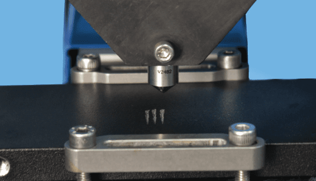
Surface engineering of materials plays a significant role in a variety of functional applications, ranging from decorative appearance to protecting the substrates from wear, corrosion and other forms of attacks. An important and overriding factor that determines the quality and service lifetime of the coatings is their cohesive and adhesive strength.

High Speed Scanning w/ Non-contact Profilometry
Introduction:
Quick and easy set-up surface measurements save time, effort and are essential for quality control, research and development and production facilities. The Nanovea Non-Contact Profilometer is capable of performing both 3D & 2D surface scans to measure nano to macro scale features on any surface, providing broad range usability.


Surface Roughness and Features of a Solar Cell
Importance of Solar Panel Testing
Maximizing a solar cell’s energy absorption is key for the technology’s survival as a renewable resource. The multiple layers of coating and glass protection allow for the absorption, transmittance, and reflection of light that is necessary for the photovoltaic cells to function. Given that most consumer solar cells operate at 15-18% efficiency, optimizing their energy output is an ongoing battle.
Studies have shown that surface roughness plays a pivotal role in the reflectance of light. The initial layer of glass must be as smooth as possible to mitigate the reflectance of light, but the subsequent layers do not follow this guideline. A degree of roughness is necessary at each coatings interface to another to increase the possibility of light scattering within their respective depletion zones and increase the absorption of light within the cell1. Optimizing the surface roughness in these regions allows the solar cell to operate to the best of its ability and with the Nanovea HS2000 High Speed Sensor, measuring surface roughness can be done quickly and accurately.
Measurement Objective
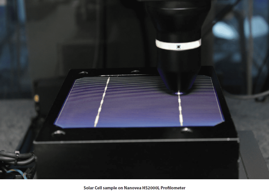
In this study we will display the capabilities of the Nanovea Profilometer HS2000 with High Speed Sensor by measuring the surface roughness and geometric features of a photovoltaic cell. For this demonstration a monocrystalline solar cell with no glass protection will be measured but the methodology can be used for various other applications.
Test Procedure and Procedures
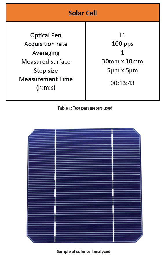
The following test parameters were used to measure the surface of the solar cell.
Results and Discussion
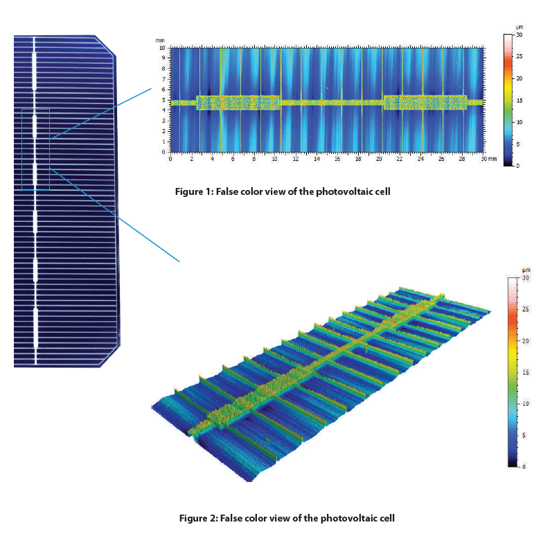
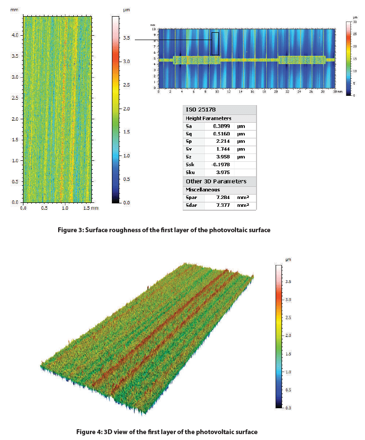
Depicted below is the 2D false-color view of the solar cell and an area extraction of the surface with its respective height parameters. A Gaussian filter was applied to both surfaces and a more aggressive index was used to flatten the extracted area. This excludes form (or waviness) larger than the cut-off index, leaving behind features that represent the solar cell’s roughness.
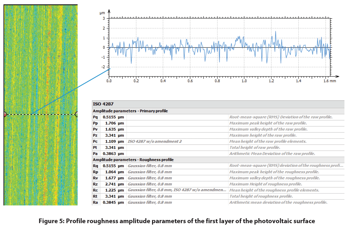
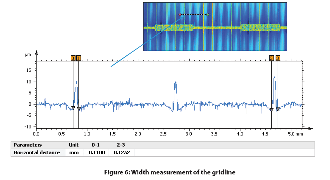
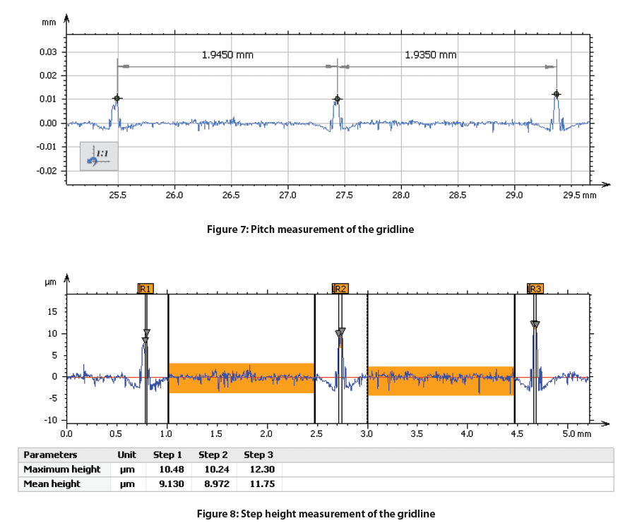
A profile was taken perpendicular to the orientation of the gridlines to measure their geometric characteristics which is shown below. The gridline width, step height, and pitch can be measured for any specific location on the solar cell.
Conclusion

In this study we were able to display the Nanovea HS2000 Line Sensor’s ability to measure a monocrystalline photovoltaic cell’s surface roughness and features. With the ability to automate accurate measurements of multiple samples and set pass fail limits, the Nanovea HS2000 Line Sensor is a perfect choice for quality control inspections.
Reference
1 Scholtz, Lubomir. Ladanyi, Libor. Mullerova, Jarmila. “Influence of Surface Roughness on Optical Characteristics of Multilayer Solar Cells “ Advances in Electrical and Electronic Engineering, vol. 12, no. 6, 2014, pp. 631-638.