USA/GLOBAL: +1-949-461-9292
EUROPE: +39-011-3052-794
CONTACT US

Category: Application Notes
 

In Situ Wear Measurement at High Temperature

IN SITU WEAR MEASUREMENT AT HIGH TEMPERATURE

USING TRIBOMETER

IN-SITU WEAR MEASUREMENT Aerospace Tribometer

Prepared by

Duanjie Li, PhD

INTRODUCTION

The Linear Variable Differential Transformer (LVDT) is a type of robust electrical transformer used to measure linear displacement. It has been widely used in a variety of industrial applications, including power turbines, hydraulics, automation, aircraft, satellites, nuclear reactors, and many others.

In this study, we feature the add-ons of LVDT and high temperature modules of the NANOVEA Tribometer which allow the change of wear track depth of the tested sample to be measured during the wear process at elevated temperatures. This enables users to correlate different stages of wear process with the evolution of COF, which is critical in improving fundamental understanding of the wear mechanism and tribological characteristics of the materials for high temperature applications.

MEASUREMENT OBJECTIVE

In this study. we would like to showcase the capacity of NANOVEA T50 Tribometer for in situ monitoring the evolution of the wear process of materials at elevated temperatures.

The wear process of the alumina silicate ceramic at different temperatures is simulated in a controlled and monitored manner.

NANOVEA

T50

TEST PROCEDURE

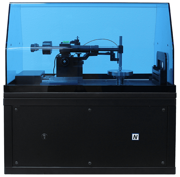
The tribological behavior, e. g. coefficient of friction, COF, and wear resistance of alumina silicate ceramic plates was evaluated by the NANOVEA Tribometer. The alumina silicate ceramic plate was heated up by a furnace from room temperature, RT, to elevated temperatures (400°C and 800°C), followed by the wear tests at such temperatures. 

For comparison, the wear tests were carried out when the sample cooled down from 800°C to 400°C and then to room temperature. An AI2O3 ball tip (6mm dia., Grade 100) was applied against the tested samples. The COF, wear depth and temperature were monitored in situ.

TEST PARAMETERS

of the pin-on-disk measurement

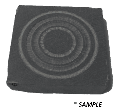
Tribometer LVDT Sample

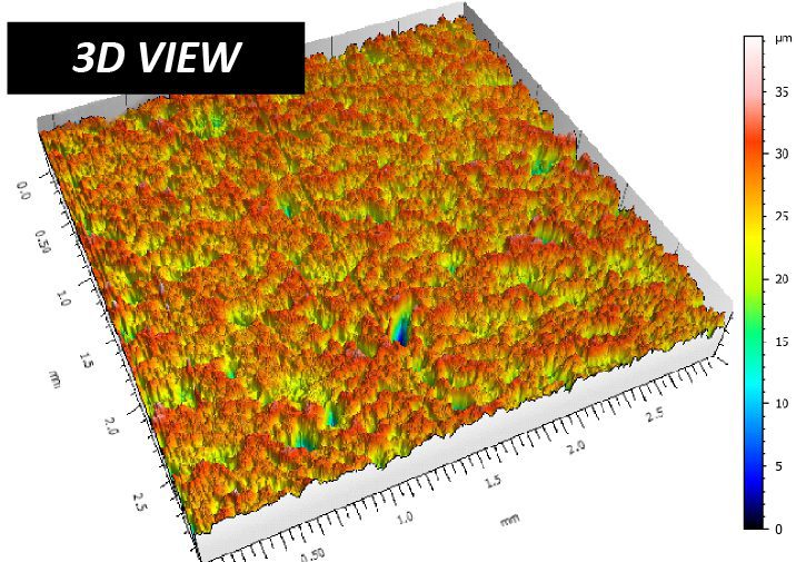
The wear rate, K, was evaluated using the formula K=V/(Fxs)=A/(Fxn), where V is the worn volume, F is the normal load, s is the sliding distance, A is the cross-sectional area of the wear track, and n is the number of revolution. Surface roughness and wear track profiles were evaluated by the NANOVEA Optical Profiler, and the wear track morphology was examined using an optical microscope.

RESULTS & DISCUSSION

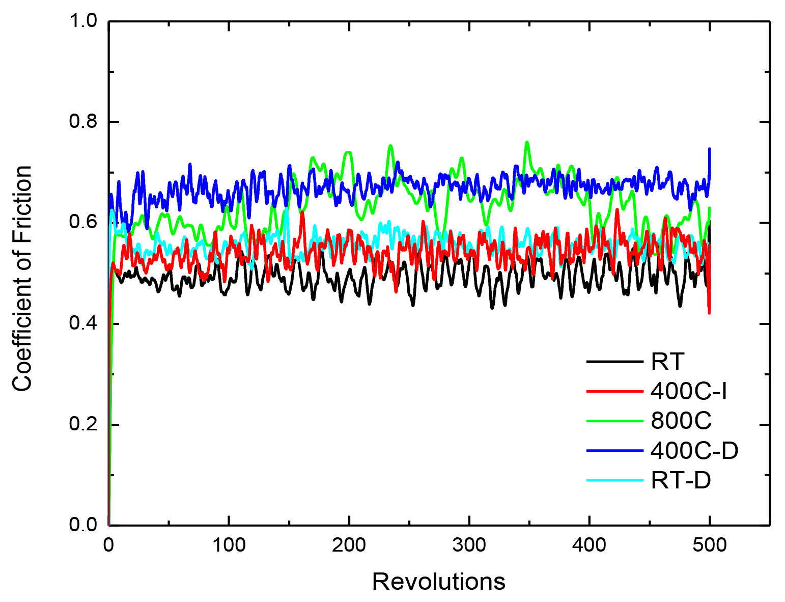
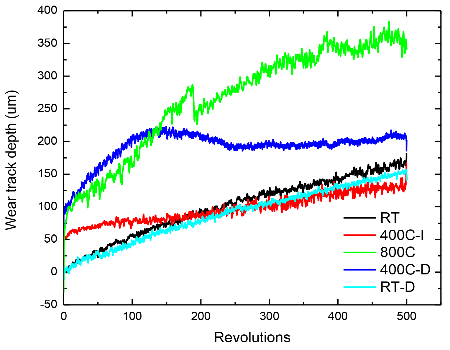
The COF and wear track depth recorded in situ are shown in FIGURE 1 and FIGURE 2, respectively. In FIGURE 1, “-I” indicates the test performed when the temperature was increased from RT to an elevated temperature. “-D” represents the temperature decreased from a higher temperature of 800°C.

As shown in FIGURE 1, the samples tested at different temperatures exhibit a comparable COF of ~0.6 throughout the measurements. Such a high COF leads to an accelerated wear process which creates a substantial amount of debris. The wear track depth was monitored during the wear tests by LVDT as shown in FIGURE 2. The tests performed at room temperature before sample heating up and after sample cooling down show that the alumina silicate ceramic plate exhibits a progressive wear process at RT, the wear track depth gradually increases throughout the wear test to ~170 and ~150 μm, respectively. 

In comparison, the wear tests at elevated temperatures (400°C and 800°C) exhibit a different wear behavior – the wear track depth increases promptly at the beginning of the wear process, and it slows down as the test continues. The wear track depths for tests performed at temperatures 400°C-I, 800°C and 400°C-D are ~140, ~350 and ~210 μm, respectively.

COF during pin-on-desk Tests at different temperatures

FIGURE 1. Coefficient of Friction during pin-on-disk tests at different temperatures

Wear track depth of the alumina silicate ceramic plate at different temperatures

FIGURE 2. Evolution of wear track depth of the alumina silicate ceramic plate at different temperatures

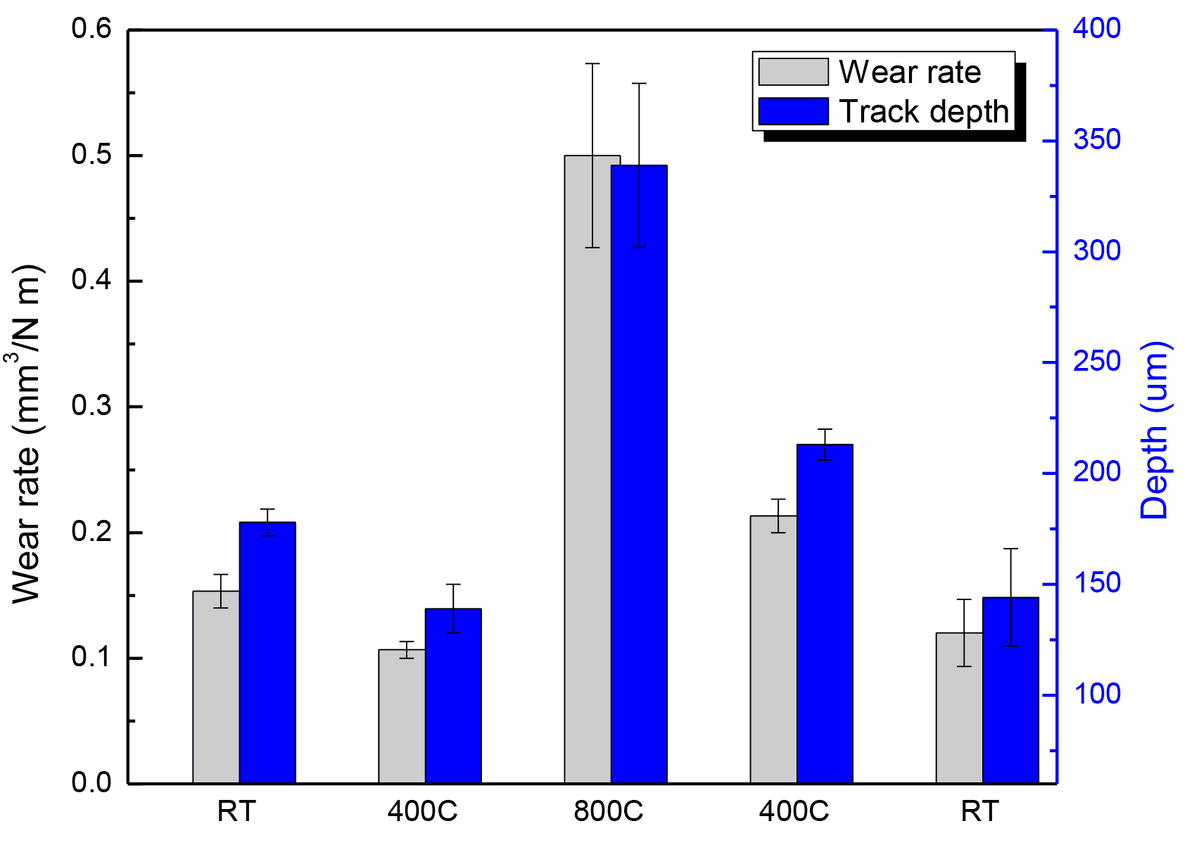
The average wear rate and wear track depth of the alumina silicate ceramic plates at different temperatures were measured using NANOVEA Optical Profiler as summarized in FIGURE 3. The wear track depth is in agreement with that recorded using LVDT. The alumina silicate ceramic plate shows a substantially increased wear rate of ~0.5 mm3/Nm at 800°C, compared to the wear rates below 0.2mm3/N at temperatures below 400°C. The alumina silicate ceramic plate does not exhibit significantly enhanced mechanical/tribological properties after the short heating process, possessing a comparable wear rate before and after the heat treatment.

Alumina silicate ceramic, also knows as lava and wonderstone, is soft and machinable before heating treatment. A long process of firing at elevated temperatures up to 1093°C can substantially enhance its hardness and strength, after which diamond machining is required. Such a unique characteristic makes alumina silicate ceramic an ideal material for sculpture.

In this study, we show that heat treatment at a lower temperature that the one required for firing (800°C vs 1093°C) in a short time does not improve the mechanical and tribological characteristics of alumina silicate ceramic, making proper firing an essential process for this material before its usage in the real applications.

 
Wear rate and wear track depth of the sample at different temperatures 1

FIGURE 3. Wear rate and wear track depth of the sample at different temperatures

CONCLUSION

Based on the comprehensive tribological analysis in this study, we show that the alumina silicate ceramic plate exhibits comparable coefficient of friction at different temperatures from room temperature to 800°C. However, it shows a substantially increased wear rate of ~0.5 mm3/Nm at 800°C, demonstrating the importance of proper heat treatment of this ceramic.

NANOVEA Tribometers are capable of evaluating the tribological properties of materials for applications at high temperatures up to 1000°C. The function of in situ COF and wear track depth measurements allows users to correlate different stages of wear process with the evolution of COF, which is critical in improving fundamental understanding of the wear mechanism and tribological characteristics of the materials used at elevated temperatures.

NANOVEA Tribometers offer precise and repeatable wear and friction testing using ISO and ASTM compliant rotative and linear modes, with optional high temperature wear, lubrication and tribo-corrosion modules available in one pre-integrated system. NANOVEA’s unmatched range is an ideal solution for determining the full range of tribological properties of thin or thick, soft or hard coatings, films and substrates.

Optional 3D Non-Contact Profilers are available for high resolution 3D imaging of wear tracks in addition to other surface measurements such as roughness.

IN-SITU WEAR MEASUREMENT

NOW, LET'S TALK ABOUT YOUR APPLICATION

Fish Scale Surface Analysis Using 3D Optical Profiler

Fish Scale Surface Analysis Using 3D Optical Profiler

Learn more


FISH SCALE SURFACE ANALYSIS

using 3D OPTICAL PROFILER

Fish Scales profilometer

Prepared by

Andrea Novitsky

INTRODUCTION

The morphology, patterns, and other features of a fish scale are studied using the NANOVEA 3D Non-Contact Optical Profiler. The delicate nature of this biological sample along with its very small and high angled grooves also highlights the importance of the profiler’s non-contact technique. The grooves on the scale are called circuli, and can be studied to estimate the age of the fish, and even distinguish periods of different rates of growth, similar to the rings of a tree. This is very important information for the management of wild fish populations in order to prevent overfishing.

Importance of 3D Non-Contact Profilometry FOR BIOLOGICAL STUDIES

Unlike other techniques such as touch probes or interferometry, the 3D Non-Contact Optical Profiler, using axial chromatism, can measure nearly any surface. Sample sizes can vary widely due to open staging and there is no sample preparation needed. Nano through macro range features are obtained during a surface profile measurement with zero influence from sample reflectivity or absorption. The instrument provides an advanced ability to measure high surface angles with no software manipulation of the results. Any material can be easily measured, whether it’s transparent, opaque, specular, diffusive, polished or rough. The technique provides an ideal, broad and user friendly capability to maximize surface studies along with the benefits of combined 2D & 3D capabilities.

MEASUREMENT OBJECTIVE

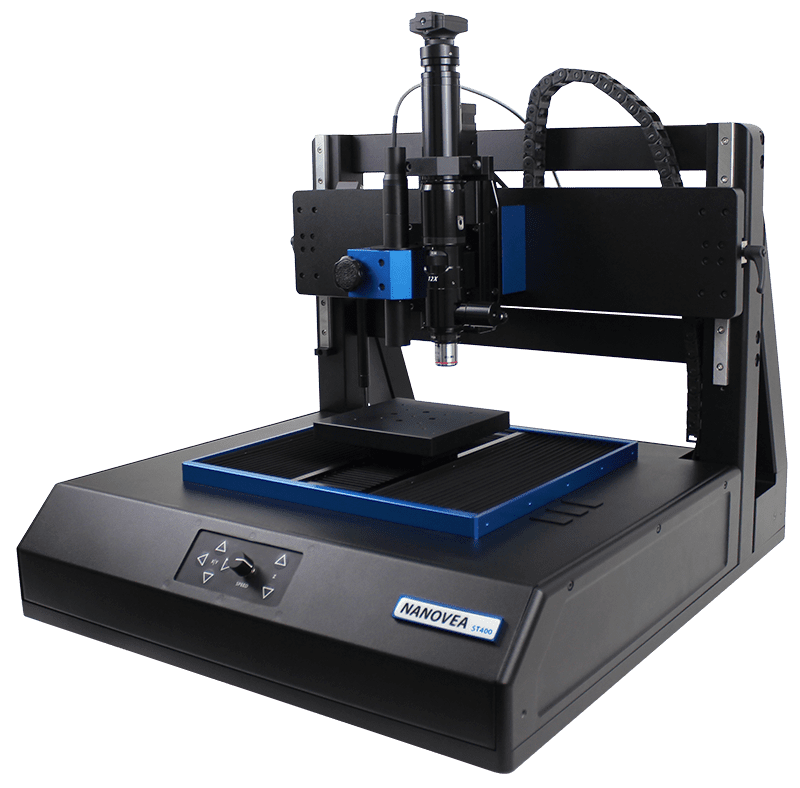
In this application, we showcase NANOVEA ST400, a 3D Non-Contact Profiler with a high-speed sensor, providing comprehensive analysis of the surface of a scale.

The instrument has been used to scan the entire sample, along with a higher resolution scan of the center area. The outer and inner side surface roughness of the scale was measured for comparison as well.

NANOVEA

ST400

3D & 2D Surface Characterization of Outer Scale

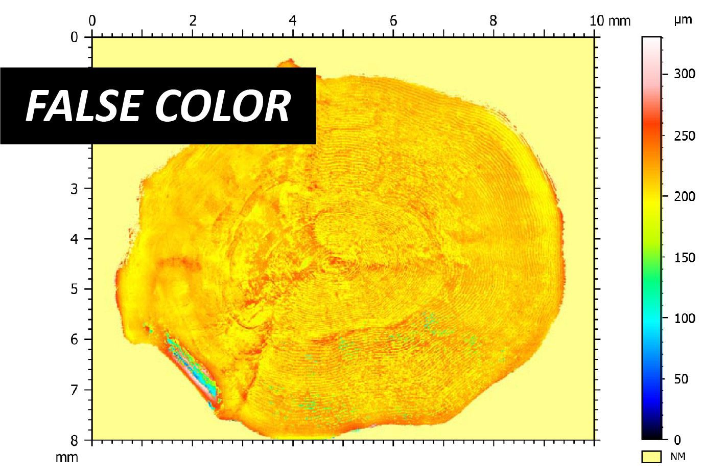
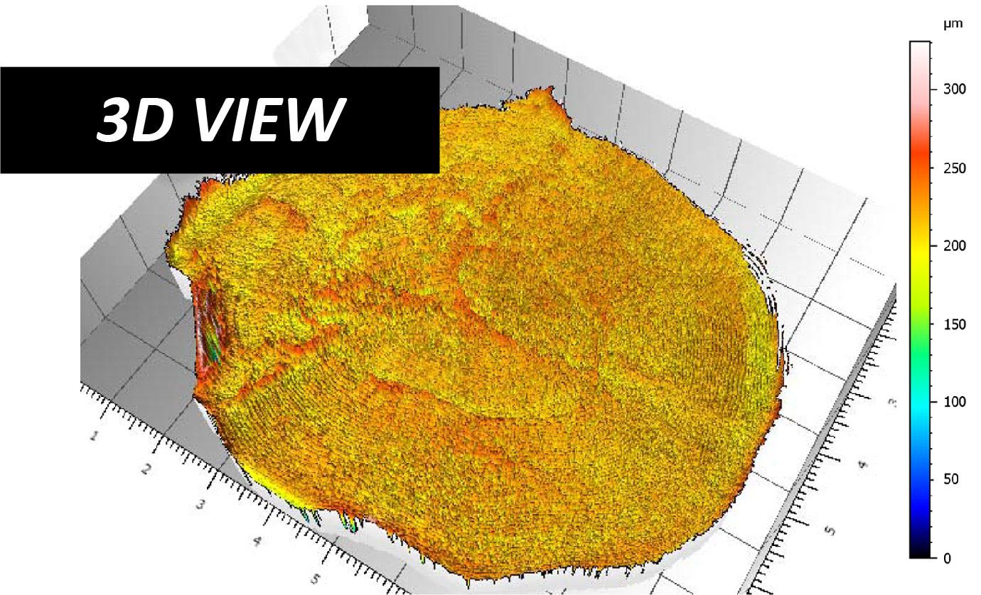
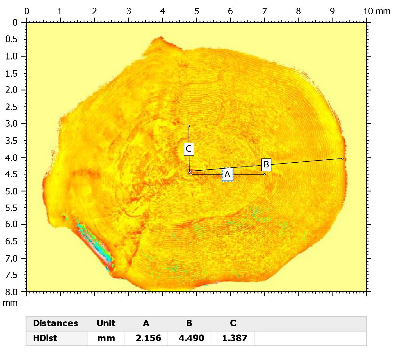
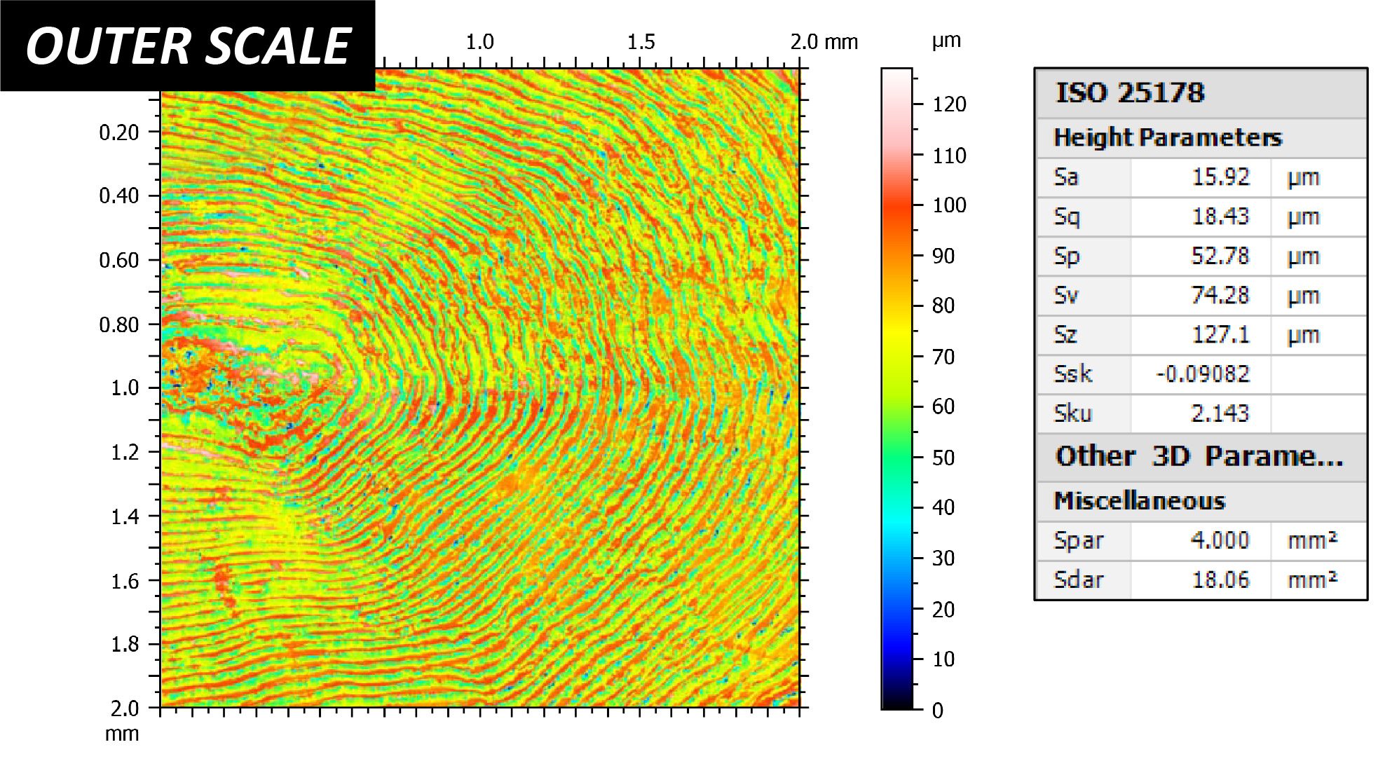
The 3D View and False Color View of the outer scale show a complex structure similar to a finger print or the rings of a tree. This provides users a straightforward tool to directly observe the surface characterization of the scale from different angles. Various other measurements of the outer scale are shown along with the comparison of the outer and inner side of the scale.

Fish Scale Scan 3D View Profilometer
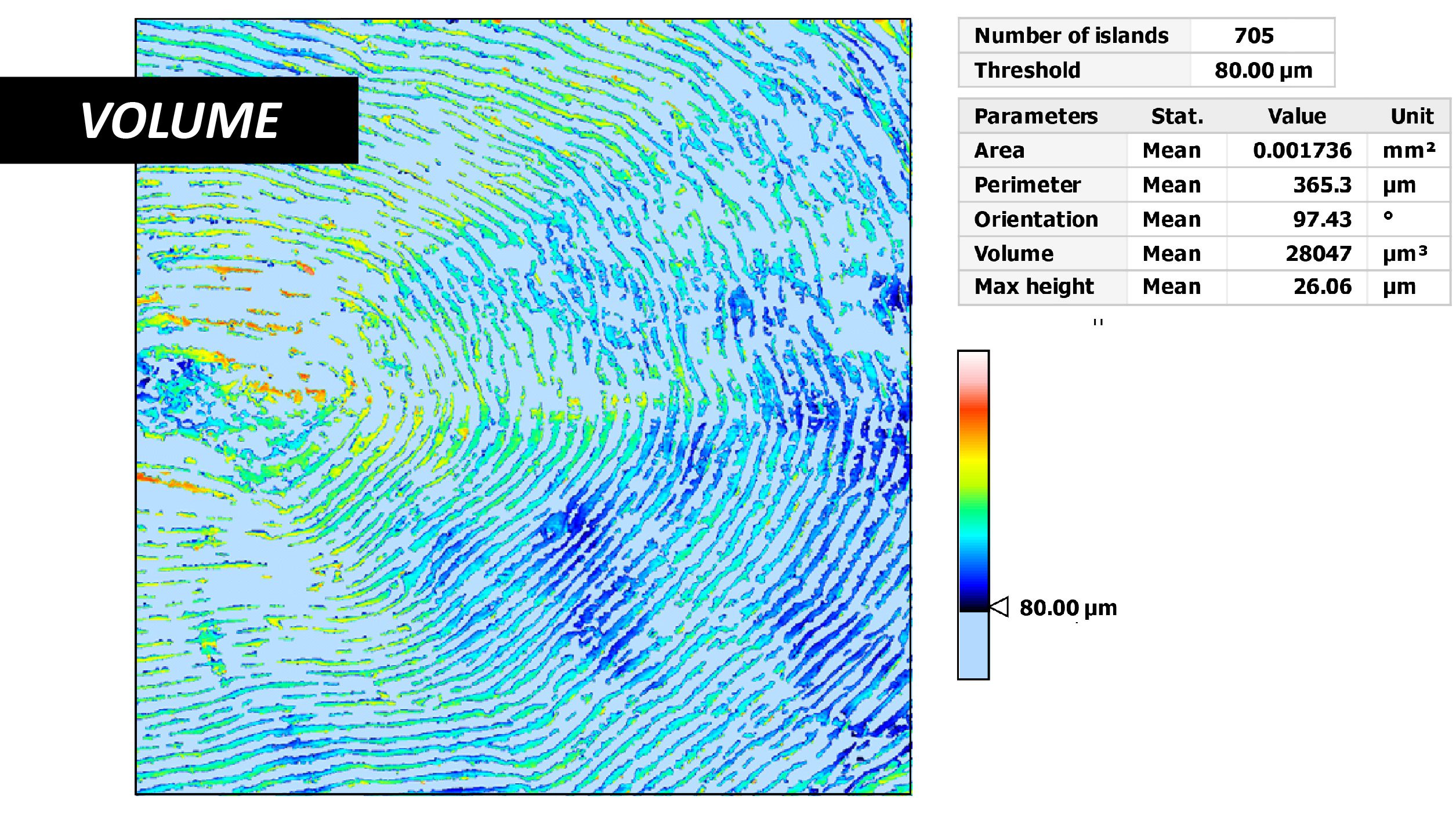
Fish Scale Scan Volume 3D Profilometer
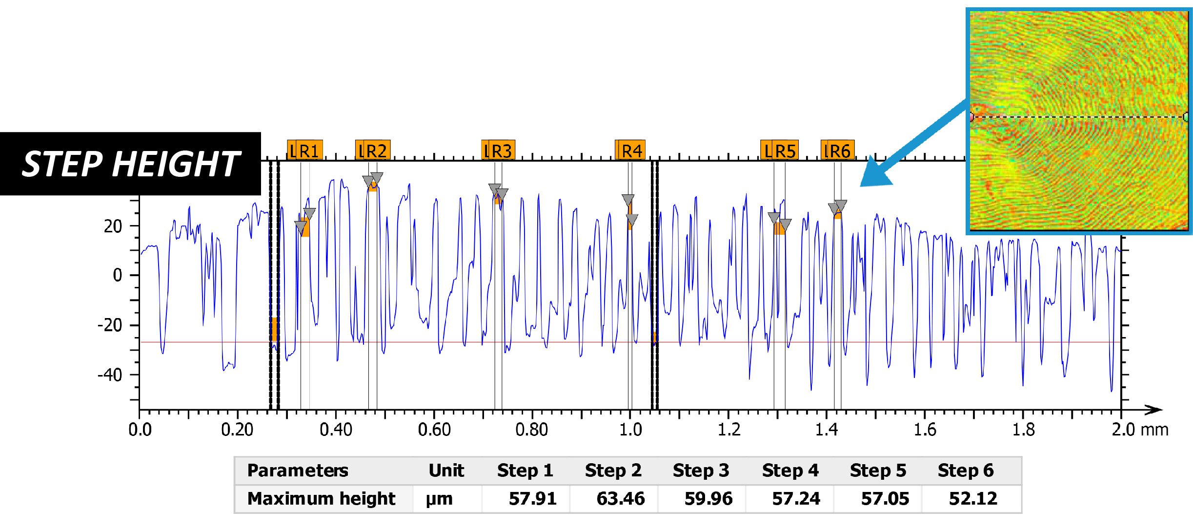
Fish Scale Scan Step Height 3D Optical Profiler

SURFACE ROUGHNESS COMPARISON

Fish Scale Profilometer 3D Scanning

CONCLUSION

In this application, we have shown how the NANOVEA 3D Non-Contact Optical Profiler can characterize a fish scale in a variety of ways. 

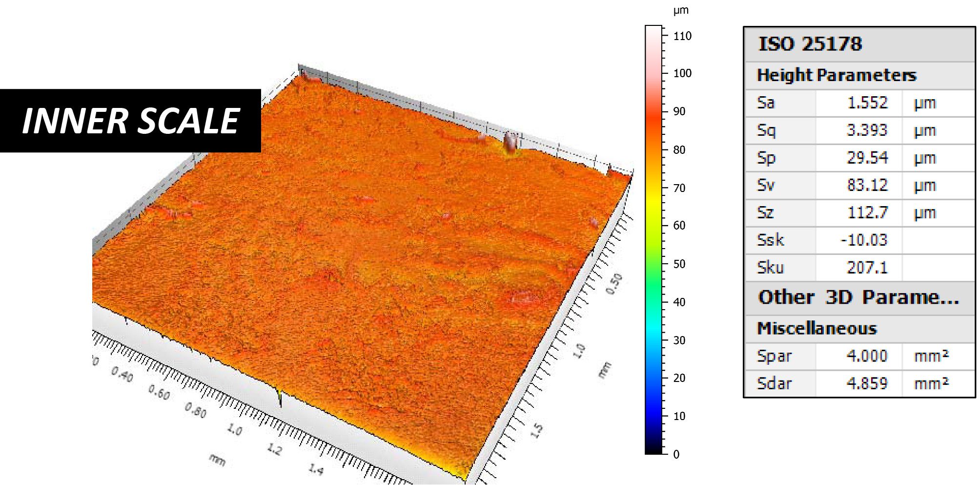
The outer and inner surfaces of the scale can be easily distinguished by surface roughness alone, with roughness values of 15.92μm and 1.56μm respectively. Additionally, precise and accurate information can be learned about a fish scale by analyzing the grooves, or circuli, on the outer surface of the scale. The distance of bands of circuli from the center focus were measured, and the height of the circuli were also found to be approximately 58μm high on average. 

The data shown here represents only a portion of the calculations available in the analysis software.

NOW, LET'S TALK ABOUT YOUR APPLICATION

Dynamic Mechanical Analysis (DMA) Frequency Sweep on Polymer


DMA FREQUENCY SWEEP

ON POLYMER USING NANOINDENTATION

Prepared by

Duanjie Li, PhD

INTRODUCTION

IMPORTANCE OF DYNAMIC MECHANICAL ANALYSIS FREQUENCY SWEEP TEST

The changing frequency of the stress often leads to variations in the complex modulus, which is a critical mechanical property of polymers. For example, tires are subjected to cyclical high deformations when vehicles are running on the road. The frequency of the pressure and deformation changes as the car accelerates to higher speeds. Such a change can result in variation in the viscoelastic properties of the tire, which are important factors in the car performance. A reliable and repeatable test of the viscoelastic behavior of polymers at different frequencies is in need. The Nano module of the NANOVEA Mechanical Tester generates sinusoidal load by a high precision piezo actuator and directly measures the evolution of force and displacement using ultrasensitive load cell and capacitor. The combination of easy setup and high accuracy makes it an ideal tool for Dynamic Mechanical Analysis frequency sweep.

Viscoelastic materials exhibit both viscous and elastic characteristics when undergoing deformation. Long molecular chains in polymer materials contribute to their unique viscoelastic properties, i.e. a combination of the characteristics of both elastic solids and Newtonian fluids. Stress, temperature, frequency and other factors all play roles in the viscoelastic properties. Dynamic Mechanical Analysis, also known as DMA, studies the viscoelastic behavior and complex modulus of the material by applying a sinusoidal stress and measuring the change of strain.

MEASUREMENT OBJECTIVE

In this application, we study viscoelastic properties of a polished tire sample at different DMA frequencies using the Most Powerful Mechanical Tester, NANOVEA PB1000, in Nanoindentation mode.

NANOVEA

PB1000

TEST CONDITIONS

FREQUENCIES (Hz):

0.1, 1.5, 10, 20

CREEP TIME AT EACH FREQ.

50 sec

OSCILLATION VOLTAGE

0.1 V

LOADING VOLTAGE

1 V

indenter type

Spherical

Diamond | 100 μm

RESULTS & DISCUSSION

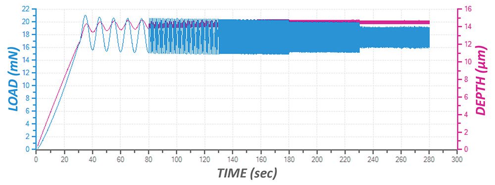
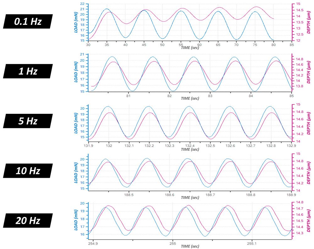
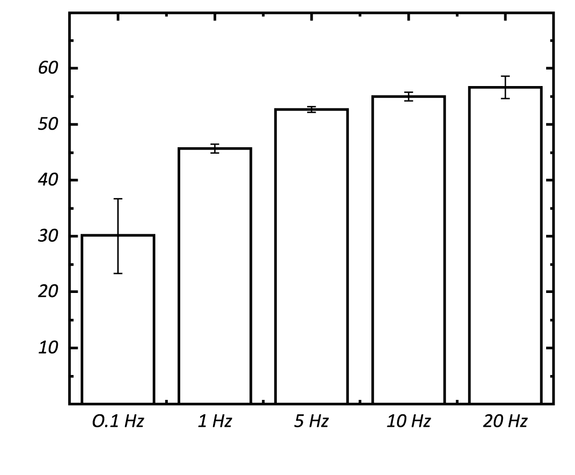
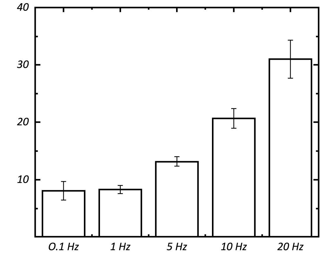
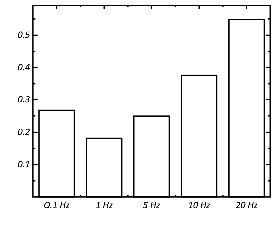
The Dynamic Mechanical Analysis frequency sweep at the maximum load allows a fast and simple measurement on the viscoelastic characteristics of the sample at different loading frequencies in one test. The phase shift and the amplitudes of the load and displacement waves at different frequencies can be used to calculate a variety of fundamental material viscoelastic properties, including Storage Modulus, Loss Modulus and Tan (δ) as summarized in the following graphs. 

Frequencies of 1, 5, 10 and 20 Hz in this study, correspond to speeds of about 7, 33, 67 and 134 km per hour. As the test frequency increases from 0.1 to 20 Hz, it can be observed that both Storage Modulus and Loss Modulus progressively increase. Tan (δ) decreases from ~0.27 to 0.18 as the frequency increases from 0.1 to 1 Hz, and then it gradually increases to ~0.55 when the frequency of 20 Hz is reached. DMA frequency sweep allows measuring the trends of Storage Modulus, Loss Modulus and Tan (δ), which provide information on the movement of the monomers and cross-linking as well as the glass transition of polymers. By raising the temperature using a heating plate during the frequency sweep, a more complete picture of the nature of the molecular motion under different test conditions can be obtained.

EVOLUTION OF LOAD & DEPTH

OF THE FULL DMA FREQUENCY SWEEP

LOAD & DEPTH vs TIME AT DIFFERENT FREQUENCIES

STORAGE MODULUS

AT DIFFERENT FREQUENCIES

LOSS MODULUS

AT DIFFERENT FREQUENCIES

TAN (δ)

AT DIFFERENT FREQUENCIES

CONCLUSION

In this study, we showcased the capacity of the NANOVEA Mechanical Tester in performing the Dynamic Mechanical Analysis frequency sweep test on a tire sample. This test measures the viscoelastic properties of the tire at different frequencies of stress. The tire shows increased storage and loss modulus as the loading frequency increases from 0.1 to 20 Hz. It provides useful information on the viscoelastic behaviors of the tire running at different speeds, which is essential in improving the performance of tires for smoother and safer rides. The DMA frequency sweep test can be performed at various temperatures to mimic the realistic working environment of the tire under different weather.

In the Nano Module of the NANOVEA Mechanical Tester, the load application with the fast piezo is independent from the load measurement done by a separate high sensitivity strain gage. This gives a distinct advantage during Dynamic Mechanical Analysis since the phase between depth and load is measured directly from the data collected from the sensor. The calculation of phase is direct and does not need mathematical modeling that adds inaccuracy to the resulting loss and storage modulus. This is not the case for a coil-based system.

In conclusion, DMA measures loss and storage modulus, complex modulus and Tan (δ) as a function of contact depth, time and frequency. Optional heating stage allows determination of materials phase transition temperature during DMA. The NANOVEA Mechanical Testers provide unmatched multi-function Nano and Micro modules on a single platform. Both the Nano and Micro modules include scratch tester, hardness tester and wear tester modes, providing the widest and most user friendly range of testing available on a single module.

NOW, LET'S TALK ABOUT YOUR APPLICATION

Fresnel Lens Topography


FRESNEL LENS

DIMENSIONS USING 3D PROFILOMETRY

Prepared by

Duanjie Li & Benjamin Mell

INTRODUCTION

A lens is an optical device of axial symmetry that transmits and refracts light. A simple lens consists of a single optical component for converging or diverging the light. Even though spherical surfaces are not ideal shape for making a lens, they are often used as the simplest shape which glass can be ground and polished to.

A Fresnel lens consists of a series of concentric rings, which are thin parts of a simple lens with a width as small as a few thousandths of an inch. Fresnel lenses contain a large aperture and short focal length, with a compact design reducing the weight and volume of material required, compared to conventional lenses with the same optical properties. A very small amount of light is lost by absorption due to the thin geometry of the Fresnel lens.

IMPORTANCE OF 3D NON-CONTACT PROFILOMETRY FOR FRESNEL LENS INSPECTION

Fresnel lenses are extensively employed in the automotive industry, lighthouses, solar energy and optical landing systems for aircraft carriers. Molding or stamping the lenses out of transparent plastics can make their production cost-effective. Service quality of Fresnel lenses mostly depends on the precision and surface quality of their concentric ring. Unlike a touch probe technique, NANOVEA Optical Profilers perform 3D surface measurements without touching the surface, avoiding the risk of making new scratches. The Chromatic Light technique is ideal for precise scanning of complex shapes, such as lenses of different geometries.

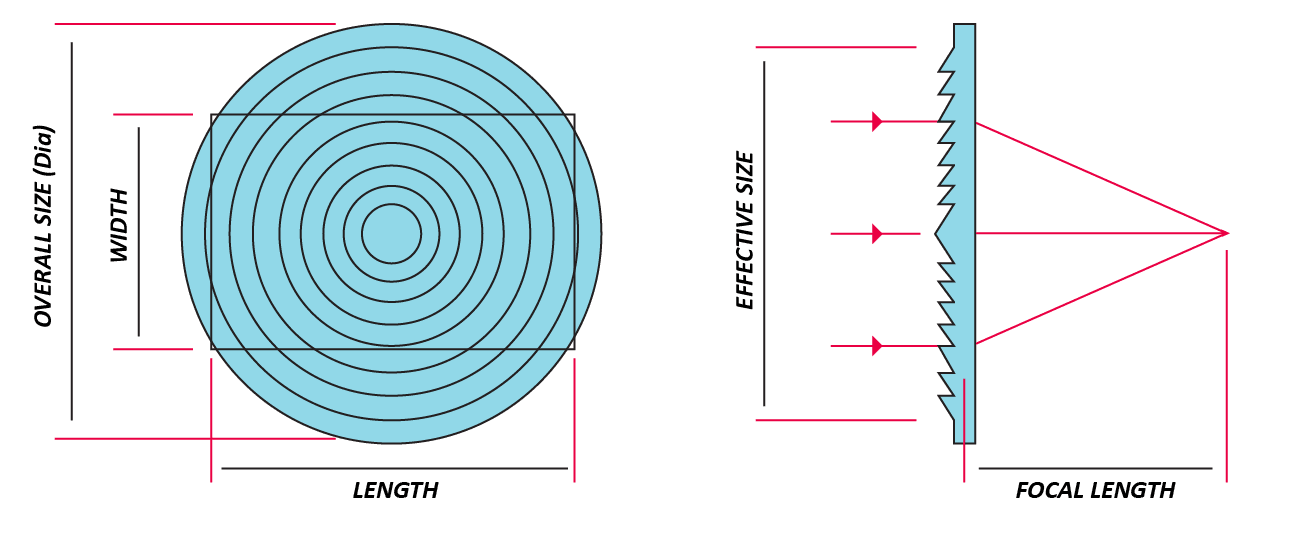
FRESNEL LENS SCHEMATIC

Transparent plastic Fresnel lenses can be manufactured by molding or stamping. Accurate and efficient quality control is critical to reveal defective production molds or stamps. By measuring the height and pitch of the concentric rings, production variations can be detected by comparing the measured values against the specification values given by the manufacturer of the lens.

Precise measurement of the lens profile ensures that the molds or stamps are properly machined to fit manufacturer specifications. Moreover, the stamp could progressively wear out over time, causing it to lose its initial shape. Consistent deviation from the lens manufacturer specification is a positive indication that the mold needs to be replaced.

MEASUREMENT OBJECTIVE

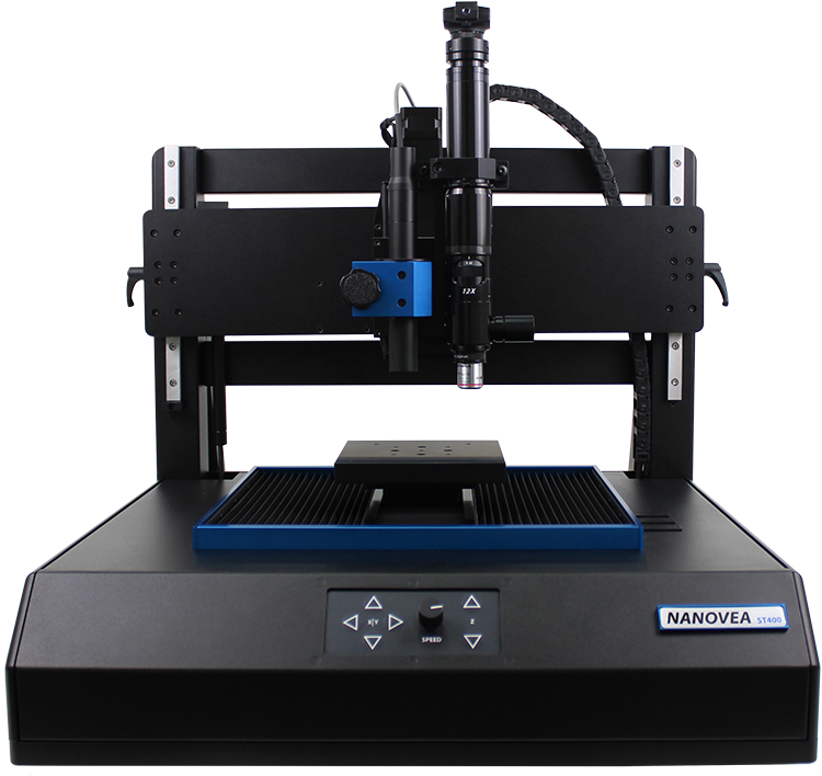
In this application, we showcase NANOVEA ST400, a 3D Non-Contact Profiler with a high-speed sensor, providing comprehensive 3D profile analysis of an optical component of a complex shape.To demonstrate the remarkable capabilities of our Chromatic Light technology, the contour analysis is performed on a Fresnel lens.

NANOVEA

ST400

The 2.3” x 2.3” acrylic Fresnel lens used for this study consists of 

a series of concentric rings and a complex serrated cross-section profile. 

It has a 1.5” focal length, 2.0” effective size diameter, 

125 grooves per inch, and an index of refraction of 1.49.

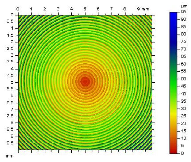
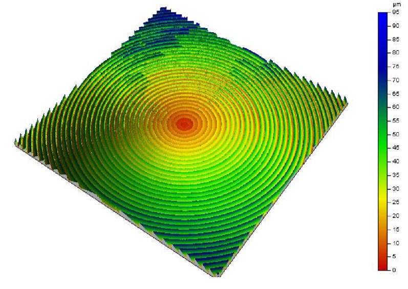
The NANOVEA ST400 scan of the Fresnel lens shows a noticeable increase in height of the concentric rings, moving outward from the center.

2D FALSE COLOR

Height Representation

3D VIEW

EXTRACTED PROFILE

PEAK & VALLEY

Dimensional Analysis of the Profile

CONCLUSION

In this application, we have showcased that the NANOVEA ST400 non-contact Optical Profiler accurately measures the surface topography of Fresnel lenses. 

The dimension of the height and pitch can be accurately determined from the complex serrated profile using NANOVEA analysis software. Users can effectively inspect the quality of the production molds or stamps by comparing the ring height and pitch dimensions of manufactured lenses against the ideal ring specification.

The data shown here represents only a portion of the calculations available in the analysis software. 

NANOVEA Optical Profilers measure virtually any surface in fields including Semiconductors, Microelectronics, Solar, Fiber Optics, Automotive, Aerospace, Metallurgy, Machining, Coatings, Pharmaceutical, Biomedical, Environmental and many others.


NOW, LET'S TALK ABOUT YOUR APPLICATION

Machined Parts QC

Machined Parts Inspection


MACHINED PARTS

inspection from CAD model using 3D profilometry

Author:

Duanjie Li, PhD

Revised by

Jocelyn Esparza

Machined Parts Inspection with a Profilometer

INTRODUCTION

The demand for precision machining able to create complex geometries has been on the rise across a spectrum of industries. From aerospace, medical and automobile, to tech gears, machinery and musical instruments, the continuous innovation and evolution push expectations and accuracy standards to new heights. Consequently, we see the rise of the demand for rigorous inspection techniques and instruments to ensure the highest quality of the products.

Importance of 3D Non-Contact Profilometry for Parts Inspection

Comparing properties of machined parts to their CAD models is essential to verify tolerances and adherence to production standards. Inspection during the service time is also crucial as wear and tear of the parts may call for their replacement. Identification of any deviations from the required specifications in a timely manner will help avoid costly repairs, production halts and tarnished reputation.

Unlike a touch probe technique, the NANOVEA Optical Profilers perform 3D surface scans with zero contact, allowing for quick, precise and non-destructive measurements of complex shapes with the highest accuracy.

MEASUREMENT OBJECTIVE

In this application, we showcase NANOVEA HS2000, a 3D Non-Contact Profiler with a high-speed sensor, performing a comprehensive surface inspection of dimension, radius, and roughness. 

All in under 40 seconds.

NANOVEA

HS2000

CAD MODEL

A precise measurement of the dimension and surface roughness of the machined part is critical to make sure it meets the desired specifications, tolerances and surface finishes. The 3D model and the engineering drawing of the part to be inspected are presented below. 

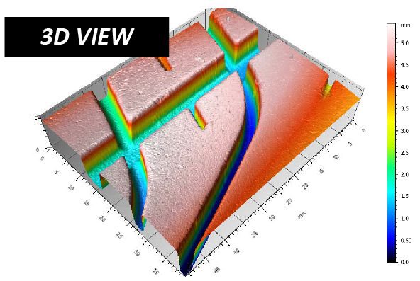
FALSE COLOR VIEW

The false color view of the CAD model and the scanned machined part surface are compared in FIGURE 3. The height variation on the sample surface can be observed by the change in color.

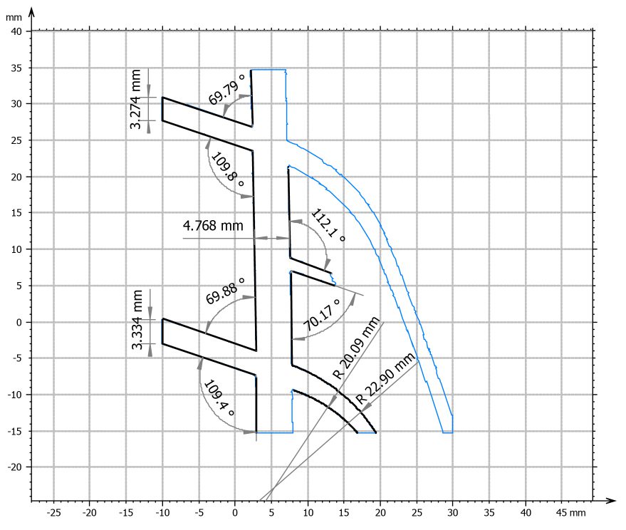
Three 2D profiles are extracted from the 3D surface scan as indicated in FIGURE 2 to further verify the dimensional tolerance of the machined part.

PROFILES COMPARISON & RESULTS

Profile 1 through 3 are shown in FIGURE 3 through 5. Quantitative tolerance inspection is carried out by comparing the measured profile with the CAD model to uphold rigorous manufacturing standards. Profile 1 and Profile 2 measure the radius of different areas on the curved machined part. The height variation of Profile 2 is 30 µm over a length of 156 mm which meets the desired ±125 µm tolerance requirement. 

By setting up a tolerance limit value, the analysis software can automatically determine pass or fail of the machined part.

Machine Parts Inspection with a Profilometer

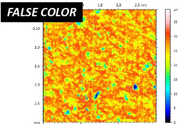
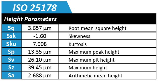
The roughness and uniformity of the machined part’s surface play an important role in ensuring its quality and functionality. FIGURE 6 is an extracted surface area from the parent scan of the machined part which was used to quantify the surface finish. The average surface roughness (Sa) was calculated to be 2.31 µm.

CONCLUSION

In this study, we have showcased how the NANOVEA HS2000 Non-Contact Profiler equipped with a high speed sensor performs comprehensive surface inspection of dimensions and roughness. 

High-resolution scans enable users to measure detailed morphology and surface features of machined parts and to quantitatively compare them with their CAD models. The instrument is also capable of detecting any defects including scratches and cracks. 

The advanced contour analysis serves as an unparalleled tool not only to determine whether the machined parts satisfy the set specifications, but also to evaluate the failure mechanisms of the worn components.

The data shown here represents only a portion of the calculations possible with the advanced analysis software that comes equipped with every NANOVEA Optical Profiler.


NOW, LET'S TALK ABOUT YOUR APPLICATION

Fretting Wear Testing Tribology

Fretting Wear Evaluation


FRETTING WEAR EVALUATION

Fretting Wear Evaluation in Aviation

Author:

Duanjie Li, PhD

Revised by

Jocelyn Esparza

Fretting Wear Evaluation in Mining and Metallurgy

INTRODUCTION

Fretting is “a special wear process that occurs at the contact area between two materials under load and subject to minute relative motion by vibration or some other force.” When machines are in operation, vibrations inevitably occur in joints that are bolted or pinned, between components that are not intended to move, and in oscillating couplings and bearings. The amplitude of such relative sliding motion is often in the order of micrometers to millimeters. Such repetitive low-amplitude motion causes serious localized mechanical wear and material transfer at the surface, which may lead to reduced production efficiency, machine performance or even damage to the machine.

Importance of Quantitative
Fretting Wear Evaluation

Fretting wear often involves several complex wear mechanisms taking place at the contact surface, including two-body abrasion, adhesion and/or fretting fatigue wear. In order to understand the fretting wear mechanism and select the best material for fretting wear protection, reliable and quantitative fretting wear evaluation is needed. The fretting wear behavior is significantly influenced by the work environment, such as displacement amplitude, normal loading, corrosion, temperature, humidity and lubrication. A versatile tribometer that can simulate the different realistic work conditions will be ideal for fretting wear evaluation.

Steven R. Lampman, ASM Handbook: Volume 19: Fatigue and Fracture
http://www.machinerylubrication.com/Read/693/fretting-wear

MEASUREMENT OBJECTIVE

In this study, we evaluated the fretting wear behaviors of a stainless steel SS304 sample at different oscillation speeds and temperatures to showcase the capacity of NANOVEA T50 Tribometer in simulating the fretting wear process of metal in a well-controlled and monitored manner.

NANOVEA

T50

TEST CONDITIONS

The fretting wear resistance of a stainless steel SS304 sample was evaluated by NANOVEA Tribometer using Linear Reciprocating Wear Module. A WC (6 mm diameter) ball was used as the counter material. The wear track was examined using a NANOVEA 3D non-contact profiler. 

The fretting test was performed at room temperature (RT) and 200 °C to study the effect of high temperature on the fretting wear resistance of the SS304 sample. A heating plate on the sample stage heated up the sample during the fretting test at 200 °C. The wear rate, K, was evaluated using the formula K=V/(F×s), where V is the worn volume, F is the normal load, and s is the sliding distance.

Please note that a WC ball as a counter material was used as an example in this study. Any solid material with different shapes and surface finish can be applied using a custom fixture to simulate the actual application situation.

TEST PARAMETERS

of the wear measurements

RESULTS & DISCUSSION

The 3D wear track profile allows direct and accurate determination of the wear track volume loss calculated by the NANOVEA Mountains analysis software. 

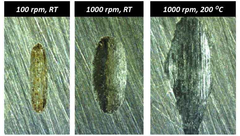
The reciprocating wear test at a low speed of 100 rpm and room temperature exhibits a small wear track of 0.014 mm³. In comparison, the fretting wear test carried out at a high speed of 1000 rpm creates a substantially larger wear track with a volume of 0.12 mm³. Such an accelerated wear process may be attributed to the high heat and intense vibration generated during the fretting wear test, which promotes oxidation of the metallic debris and results in severe three-body abrasion. The fretting wear test at an elevated temperature of 200 °C forms a larger wear track of 0.27 mm³.

The fretting wear test at 1000 rpm has a wear rate of 1.5×10⁻⁴ mm³/Nm, which is nearly nine times compared to that in a reciprocating wear test at 100 rpm. The fretting wear test at an elevated temperature further accelerates the wear rate to 3.4×10⁻⁴ mm³/Nm. Such a significant difference in wear resistance measured at different speeds and temperatures shows the importance of proper simulations of fretting wear for realistic applications.

Wear behavior can change drastically when small changes in testing conditions are introduced into the tribosystem. The versatility of the NANOVEA Tribometer allows measuring wear under various conditions, including high temperature, lubrication, corrosion and others. The accurate speed and position control by the advanced motor enables users to perform the wear test at speeds ranging from 0.001 to 5000 rpm, making it an ideal tool for research/testing labs to investigate the fretting wear in different tribological conditions.

Fretting wear tracks at various conditions

under the optical microscope

Fretting wear tracks at various conditions under the optical microscope

3D WEAR TRACKs PROFILES

provide more insight in fundamental understanding
of the fretting wear mechanism

3d wear track profiles - fretting

RESULT SUMMARY OF WEAR TRACKS

measured using different test parameters

CONCLUSION

In this study, we showcased the capacity of the NANOVEA Tribometer in evaluating the fretting wear behavior of a stainless steel SS304 sample in a well-controlled and quantitative manner. 

The test speed and temperature play critical roles in the fretting wear resistance of the materials. The high heat and intense vibration during the fretting resulted in substantially accelerated wear of the SS304 sample by close to nine times. The elevated temperature of 200 °C further increased the wear rate to 3.4×10⁻⁴ mm3/Nm. 

The versatility of the NANOVEA Tribometer makes it an ideal tool for measuring fretting wear under various conditions, including high temperature, lubrication, corrosion and others.

NANOVEA Tribometers offer precise and repeatable wear and friction testing using ISO and ASTM compliant rotative and linear modes, with optional high temperature wear, lubrication and tribo-corrosion modules available in one pre-integrated system. Our unmatched range is an ideal solution for determining the full scope of tribological properties of thin or thick, soft or hard coatings, films and substrates.

NOW, LET'S TALK ABOUT YOUR APPLICATION

Pharmaceutical Tablets Surface Roughness Inspection


Pharmaceutical Tablets

Inspecting Roughness using 3d profilometers

Author:

Jocelyn Esparza

Introduction

Pharmaceutical tablets are the most popular medicinal dosage used today. Each tablet is made up by a combination of active substances (the chemicals that produce pharmacological effect) and inactive substances (disintegrant, binder, lubricant, diluent – usually in the form of powder). The active and inactive substances are then compressed or molded into a solid. Then, depending on the manufacturer specifications, the tablets are either coated or uncoated.

To be effective, tablet coatings need to follow the fine contours of embossed logos or characters on tablets, they need to be stable and sturdy enough to survive handling of the tablet, and they must not cause the tablets to stick to each other during the coating process. Current tablets typically have a polysaccharide and polymer-based coating which include substances like pigments and plasticizers. The two most common types of table coatings are film coatings and sugar coating. Compared to sugar coatings, film coatings are less bulky, more durable, and are less time-consuming to prepare and apply. However, film coatings have more difficulty hiding tablet appearance.

Tablet coatings are essential for moisture protection, masking the taste of the ingredients, and making the tablets easier to swallow. More importantly, the tablet coating controls the location and the rate in which the drug is released.

MEASUREMENT OBJECTIVE

In this application, we use the NANOVEA Optical Profiler and advanced Mountains software to measure and quantify the topography of various name brand pressed pills (1 coated and 2 uncoated) to compare their surface roughness.

It is assumed that Advil (coated) will have the lowest surface roughness due to the protective coating it has.

NANOVEA

HS2000

Test Conditions

Three batches of name brand pharmaceutical pressed tablets were scanned with the Nanovea HS2000
using High-Speed Line Sensor to measure various surface roughness parameters according to ISO 25178.

Scan Area

2 x 2 mm

Lateral Scan Resolution

5 x 5 μm

Scan Time

4 sec

Samples

Results & Discussion

After scanning the tablets, a surface roughness study was conducted with the advanced Mountains analysis software to calculate the surface average, root-mean-square, and maximum height of each tablet.

The calculated values support the assumption that Advil has a lower surface roughness due to the protective coating encasing its ingredients. Tylenol shows to have the highest surface roughness out of all three measured tablets.

A 2D and 3D height map of each tablet’s surface topography was produced which show the height distributions measured. One out of the five tablets were selected to represent the height maps for each brand. These height maps make a great tool for visual detection of outlying surface features such as pits or peaks.

Conclusion

In this study, we analyzed and compared the surface roughness of three name brand pressed pharmaceutical pills: Advil, Tylenol, and Excedrin. Advil proved to have the lowest average surface roughness. This can be attributed to the presence of the orange coating incasing the drug. In contrast, both Excedrin and Tylenol lack coatings, however, their surface roughness still differ from each other. Tylenol proved to have the highest average surface roughness out of all the tablets studied.

Using the NANOVEA HS2000 with High-Speed Line Sensor, we were able to measure 5 tablets in less than 1 minute. This can prove to be useful for quality control testing of hundreds of pills in a production today.

NOW, LET'S TALK ABOUT YOUR APPLICATION

Microparticles: Compression Strength and Micro Indentation

 

MICROPARTICLES

COMPRESSION STRENGTH & MICRO INDENTATION
BY TESTING SALTS​

Author:
Jorge Ramirez

Revised by:
Jocelyn Esparza

INTRODUCTION

Compression strength has become vital to quality control measurement in developing and improving new and existing microparticles and micro features (pillars and spheres) seen today. Microparticles have various shapes, sizes and can be developed from ceramics, glass, polymers, and metals. Uses include drug delivery, food flavor enhancement, concrete formulations among many others. Controlling the mechanical properties of microparticles or microfeatures are critical for their success and requires the ability to quantitatively characterize their mechanical integrity  

IMPORTANCE OF DEPTH VERSUS LOAD COMPRESSION STRENGTH

Standard compressive measurement instruments are not capable of low loads and fail to provide adequate depth data for microparticles. By using Nano or Microindentation, the compression strength of nano or microparticles (soft or hard) can be accurately and precisely measured.  

MEASUREMENT OBJECTIVE

In this application note we measure  the compression strength of salt with the NANOVEA Mechanical Tester in micro indentation mode.

NANOVEA

CB500

TEST CONDITIONS

maximum force

30 N

loading rate

60 N/min

unloading rate

60 N/min

indenter type

Flat Punch

Steel | 1mm Diameter

Load vs depth curves

Results & Discussion

Height, failure force and strength for Particle 1 and Particle 2

Particle failure was determined to be the point where the initial slope of the force vs. depth curve began to noticeably decrease.This behavior shows the material has reached a yield point and is no longer able to resist the compressive forces being applied. Once the yield point is surpassed, the indentation depth begins to exponentially increase for the duration of the loading period. These behaviors can be seen in Load vs Depth Curves for both samples.

CONCLUSION

In conclusion, we have shown how the NANOVEA Mechanical Tester in micro indentation mode is a great tool for compression strength testing of microparticles. Although the particles tested are made of the same material, it is suspected that the different failure points measured in this study were likely due to pre-existent micro cracks in the particles and varying particle sizes. It should be noted that for brittle materials, acoustic emission sensors are available to measure the beginning of crack propagation during a test.


The
NANOVEA Mechanical Tester offers depth displacement resolutions down to the sub nanometer level,
making it a great tool for the study of very fragile micro particles or features as well. For soft and fragile
materials, loads down to 0.1mN are possible with our nano indentation module

NOW, LET'S TALK ABOUT YOUR APPLICATION

Ball Bearings: High Force Wear Resistance Study


INTRODUCTION

A ball bearing uses balls to reduce rotational friction and support radial and axial loads. The rolling balls between the bearing races produce much lower coefficient of friction (COF) compared to two flat surfaces sliding against each other. Ball bearings are often exposed to high contact stress levels, wear and extreme environmental conditions such as high temperatures. Therefore, wear resistance of the balls under high loads and extreme environmental conditions is critical for extending the lifetime of the ball bearing to cut down cost and time on repairs and replacements.
Ball bearings can be found in nearly all applications that involve moving parts. They are commonly used in transportation industries such as aerospace and automobile as well as the toy industry that manufactures items such as fidget spinner and skateboards.

BALL BEARING WEAR EVALUATION AT HIGH LOADS

Ball bearings can be made from an extensive list of materials. Commonly used materials range between metals like stainless steel and chrome steel or ceramics such as tungsten carbide (WC) and silicon nitride (Si3n4). To ensure that the manufactured ball bearings possess the required wear resistance ideal for the given application’s conditions, reliable tribological evaluations under high loads are necessary. Tribological testing aids in quantifying and contrasting the wear behaviors of diff­erent ball bearings in a controlled and monitored manner to select the best candidate for the targeted application.

MEASUREMENT OBJECTIVE

In this study, we showcase a Nanovea Tribometer as the ideal tool for comparing the wear resistance of different ball bearings under high loads.

Figure 1:  Setup of the bearing test.

TESTING PROCEDURE

The coefficient of friction, COF, and the wear resistance of the ball bearings made of different materials were evaluated by a Nanovea Tribometer. P100 grit sandpaper was used as the counter material. The wear scars of the ball bearings were examined using a Nanovea 3D Non-Contact Profiler after the wear tests concluded. The test parameters are summarized in Table 1. The wear rate, K, was evaluated using the formula K=V/(F×s), where V is the worn volume, F is the normal load and s is the sliding distance. Ball wear scars were evaluated by a Nanovea 3D Non-Contact Profiler to ensure precise wear volume measurement.
The automated motorized radial positioning feature allows the tribometer to decrease the radius of the wear track for the duration of a test. This test mode is called a spiral test and it ensures that the ball bearing always slides on a new surface of the sandpaper (Figure 2). It significantly improves the repeatability of the wear resistance test on the ball. The advanced 20bit encoder for internal speed control and 16bit encoder for external position control provide precise real-time speed and position information, allowing for a continuous adjustment of rotational speed to achieve constant linear sliding speed at the contact.
Please note that P100 Grit sandpaper was used to simplify the wear behavior between various ball materials in this study and can be substituted with any other material surface. Any solid material can be substituted to simulate the performance of a wide range of material couplings under actual application conditions, such as in liquid or lubricant.

Figure 2:  Illustration of the spiral passes for the ball bearing on the sandpaper.
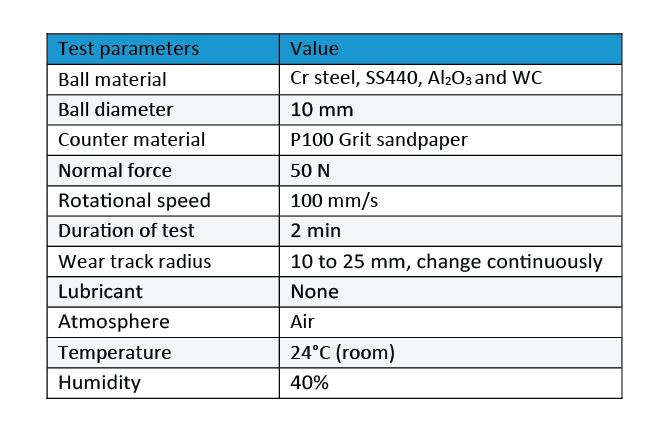
Table 1:  Test parameters of the wear measurements.


RESULTS & DISCUSSION

Wear rate is a vital factor for determining the service lifetime of the ball bearing, while a low COF is desirable to improve the bearing performance and efficiency. Figure 3 compares the evolution of COF for di­fferent ball bearings against the sandpaper during the tests. The Cr Steel ball shows an increased COF of ~0.4 during the wear test, compared to ~0.32 and ~0.28 for SS440 and Al2O3 ball bearings. On the other hand, the WC ball exhibits a constant COF of ~0.2 throughout the wear test. Observable COF variation can be seen throughout each test which is attributed to vibrations caused by the sliding movement of the ball bearings against the rough sandpaper surface.


Figure 3:  Evolution of COF during the wear tests.

Figure 4 and Figure 5 compare the wear scars of the ball bearings after they were measured by an optical microscope and Nanovea Non-Contact optical profiler, respectively, and Table 2 summarizes the results of the wear track analysis. The Nanovea 3D profiler precisely determines the wear volume of the ball bearings, making it possible to calculate and compare the wear rates of different ball bearings. It can be observed that the Cr Steel and SS440 balls exhibit much larger flattened wear scars compared to the ceramic balls, i.e. Al2O3 and WC after the wear tests. The Cr Steel and SS440 balls have comparable wear rates of 3.7×10⁻³ and 3.2×10⁻³ m3/N m, respectively. In comparison, the Al2O3 ball shows an enhanced wear resistance with a wear rate of 7.2×10⁻⁴ m3/N m. The WC ball barely exhibits minor scratches on the shallow wear track area, resulting in a significantly reduced wear rate of 3.3×10⁻⁶ mm3/N m.
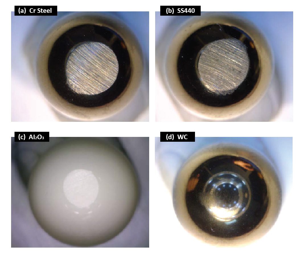
Figure 4:  Wear scars of the ball bearings after the tests.
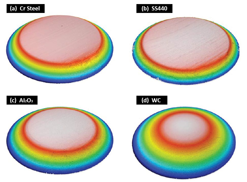
Figure 5:  3D morphology of the wear scars on the ball bearings.
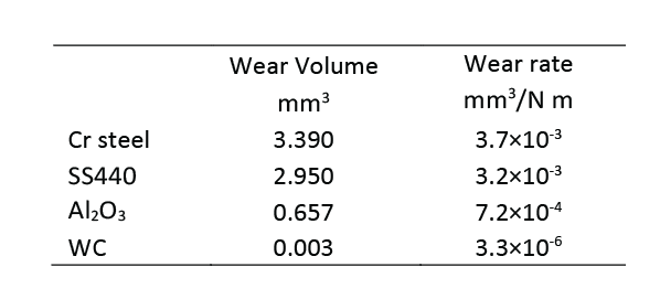
Table 2: Wear scar analysis of the ball bearings.

Figure 6 shows microscope images of the wear tracks produced on the sand paper by the four ball bearings. It is evident that the WC ball produced the most severe wear track (removing almost all sand particle in its path) and possesses the best wear resistance. In comparison, the Cr Steel and SS440 balls left a large amount of metal debris on the wear track of the sand paper.
These observations further demonstrate the importance of the benefit of a spiral test. It ensures that the ball bearing always slides on a new surface of the sandpaper, which significantly improves the repeatability of a wear resistance test.

Figure 6:  Wear tracks on the sand paper against different ball bearings.

CONCLUSION

The wear resistance of the ball bearings under a high pressure plays a vital role in their service performance. The ceramic ball bearings possess significantly enhanced wear resistance under high stress conditions and reduce the time and cost due to bearing repairing or replacement. In this study, the WC ball bearing exhibits a substantially higher wear resistance compared to the steel bearings, making it an ideal candidate for bearing applications where severe wear takes place.
A Nanovea Tribometer is designed with high torque capabilities for loads up to 2000 N and precise and controlled motor for rotational speeds from 0.01 to 15,000 rpm. It offers repeatable wear and friction testing using ISO and ASTM compliant rotative and linear modes, with optional high temperature wear and lubrication modules available in one pre-integrated system. This unmatched range allows users to simulate different severe work environments of the ball bearings including high stress, wear and high temperature, etc. It also acts as an ideal tool to quantitatively assess the tribological behaviors of superior wear resistant materials under high loads.
A Nanovea 3D Non-Contact Profiler provides precise wear volume measurements and acts as a tool to analyze the detailed morphology of the wear tracks, providing additional insights in the fundamental understanding of wear mechanisms.

Prepared by
Duanjie Li, PhD, Jonathan Thomas, and Pierre Leroux

Dental-Screws-dimensional-measurement-using-3d-profilometer

Dental Tools: Dimensional and Surface Roughness Analysis


INTRODUCTION


Having precise dimensions and optimal surface roughness are vital to the functionality of dental screws. Many dental screw dimensions require high precision such as radii, angles, distances, and step heights. Understanding local surface roughness is also highly important for any medical tool or part being inserted inside the human body to minimize sliding friction.


NON-CONTACT PROFILOMETRY FOR DIMENSIONAL STUDY


Nanovea 3D Non-Contact Profilers use a chromatic light-based technology to measure any material surface: transparent, opaque, specular, diffusive, polished or rough. Unlike a touch probe technique, the non-contact technique can measure inside tight areas and will not add any intrinsic errors due to deformation caused by the tip pressing on a softer plastic material.  Chromatic light-based technology also offers superior lateral and height accuracies compared to focus variation technology. Nanovea Profilers can scan large surfaces directly without stitching and profile the length of a part in a few seconds. Nano through macro range surface features and high surface angles can be measured due to the profiler’s ability to measure surfaces without any complex algorithms manipulating the results.


MEASUREMENT OBJECTIVE


In this application, the Nanovea ST400 Optical Pro­filer was used to measure a dental screw along flat and thread features in a single measurement. The surface roughness was calculated from the flat area, and various dimensions of the threaded features were determined.


dental screw quality control

Sample of dental screw analyzed by NANOVEA Optical Profiler.


Dental screw sample analyzed.


RESULTS


3D Surface

The 3D View and False Color View of the dental screw shows a flat area with threading starting on either side. It provides users a straightforward tool to directly observe the morphology of the screw from different angles. The flat area was extracted from the full scan to measure its surface roughness.


2D Surface Analysis

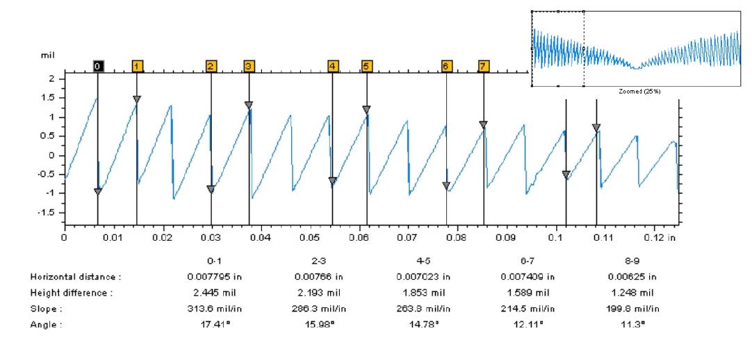
Line profiles can also be extracted from the surface to show a cross-sectional view of the screw. The Contour Analysis and step height studies were used to measure precise dimensions at a certain location on the screw.


CONCLUSION


In this application, we have showcase the Nanovea 3D Non-Contact Profiler’s ability to precisely calculate local surface roughness and measure large dimensional features in a single scan.

The data shows a local surface roughness of 0.9637 μm. The radius of the screw between threads was found to be 1.729 mm, and the threads had an average height of 0.413 mm. The average angle between the threads was determined to be 61.3°.

The data shown here represents only a portion of the calculations available in the analysis software.


Prepared by
Duanjie Li, PhD., Jonathan Thomas, and Pierre Leroux