USA/GLOBAL: +1-949-461-9292
EUROPE: +39-011-3052-794
CONTACT US

Category: Mechanical Testing


Creep Deformation of Polymers using Nanoindentation

Creep Deformation of Polymers using Nanoindentation

Learn more


CREEP DEFORMATION

OF POLYMERS USING NANOINDENTATION

Prepared by

DUANJIE LI, PhD

INTRODUCTION

As viscoelastic materials, polymers often undergo a time-dependent deformation under a certain applied load, also known as creep. Creep becomes a critical factor when the polymeric parts are designed to be exposed to continuous stress, such as structural components, joins and fittings, and hydrostatic pressure vessels.

IMPORTANCE OF CREEP MEASUREMENT FOR POLYMERS

The inherent nature of viscoelasticity plays a vital role in the performance of polymers and directly influences their service reliability. The environmental conditions such as loading and temperature affect the creep behavior of the polymers. Creep failures often occur due to the lack of alertness of the time-dependent creep behavior of the polymer materials used under specific service conditions. As a result, it is important to develop a reliable and quantitative test of the viscoelastic mechanical behaviors of the polymers. The Nano module of the NANOVEA Mechanical Testers applies the load with a high-precision piezo and directly measures the evolution of force and displacement in situ. The combination of accuracy and repeatability makes it an ideal tool for creep measurement.

MEASUREMENT OBJECTIVE

In this application, we showcased that
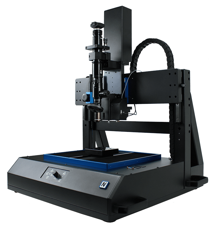
the NANOVEA PB1000 Mechanical Tester
in Nanoindentation mode is an ideal tool
for studying viscoelastic mechanical properties
including hardness, Young’s modulus
and creep of polymeric materials.

NANOVEA

PB1000

TEST CONDITIONS

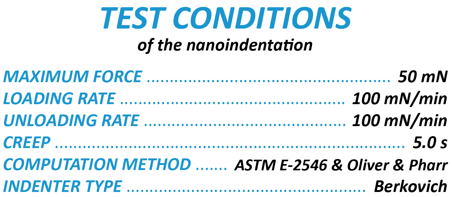
Eight different polymer samples were tested by nanoindentation technique using the NANOVEA PB1000 Mechanical Tester. As the load linearly increased from 0 to 40 mN, the depth progressively increased during the loading stage. The creep was then measured by the change of indentation depth at the maximum load of 40 mN for 30 s.

MAXIMUM LOAD 40 mN
LOADING RATE
80 mN/min
UNLOADING RATE 80 mN/min
CREEP TIME
30 s

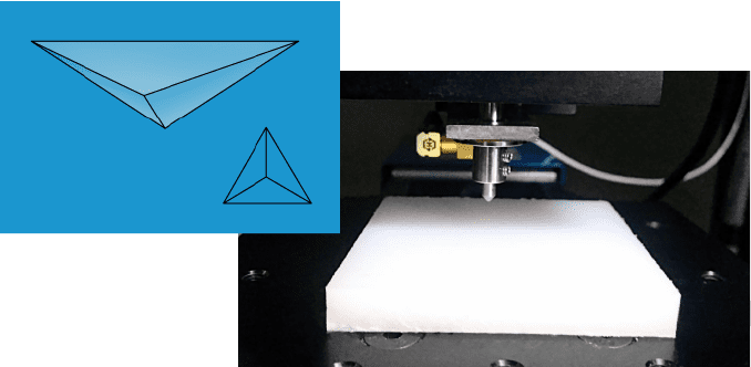
INDENTER TYPE

Berkovich

Diamond

*setup of the nanoindentation test

RESULTS & DISCUSSION

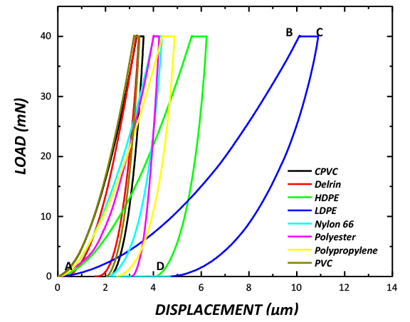
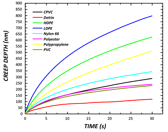
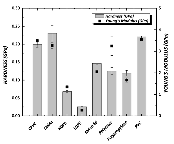
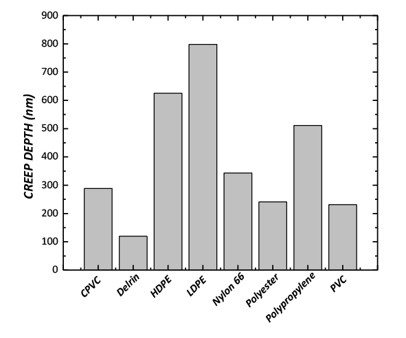
The load vs displacement plot of the nanoindentation tests on different polymer samples is shown in FIGURE 1 and the creep curves are compared in FIGURE 2. The hardness and Young’s modulus are summarized in  FIGURE 3, and the creep depth is shown in FIGURE 4. As an examples in FIGURE 1, the AB, BC and CD portions of the load-displacement curve for the nanoindentation measurement represent the loading, creep and unloading processes, respectively.

Delrin and PVC exhibit the highest hardness of 0.23 and 0.22 GPa, respectively, while LDPE possesses the lowest hardness of 0.026 GPa among the tested polymers. In general, the harder polymers show lower creep rates. The softest LDPE has the highest creep depth of 798 nm, compared to ~120 nm for Delrin.

The creep properties of the polymers are critical when they are used in structural parts. By precisely measuring the hardness and creep of the polymers, a better understanding of the time-dependent reliability of the polymers can be obtained. The creep, change of the displacement at a given load, can also be measured at different elevated temperatures and humidity using the NANOVEA PB1000 Mechanical Tester, providing an ideal tool to quantitatively and reliably measure the viscoelastic mechanical behaviors of polymers
in the simulated realistic application environment.

FIGURE 1: The load vs displacement plots
of different polymers.

FIGURE 2: Creeping at a maximum load of 40 mN for 30 s.

FIGURE 3: Hardness and Young’s modulus of the polymers.

FIGURE 4: Creep depth of the polymers.

CONCLUSION

In this study, we showcased that the NANOVEA PB1000
Mechanical Tester measures the mechanical properties of different polymers, including hardness, Young’s modulus and creep. Such mechanical properties are essential in selecting the proper polymer material for intended applications. Derlin and PVC exhibit the highest hardness of 0.23 and 0.22 GPa, respectively, while LDPE possesses the lowest hardness of 0.026 GPa among the tested polymers. In general, the harder polymers exhibit lower creep rates. The softest LDPE shows the highest creep depth of 798 nm, compared to ~120 nm for Derlin.

The NANOVEA Mechanical Testers provide unmatched multi-function Nano and Micro modules on a single platform. Both the Nano and Micro modules include scratch tester, hardness tester and wear tester modes, providing the wildest and most user-friendly range of testing available on a single system.

NOW, LET'S TALK ABOUT YOUR APPLICATION

Multiphase Material using Nanoindentation NANOVEA

Multiphase Metal Nanoindentation

Metallurgy Study of Multiphase Material using Nanoindentation

Learn more


METALLURGY STUDY
OF MULTIPHASE MATERIAL

USING NANOINDENTATION

Prepared by

DUANJIE LI, PhD & ALEXIS CELESTIN

INTRODUCTION

Metallurgy studies the physical and chemical behavior of metallic elements, as well as their intermetallic compounds and alloys. Metals that undergo working processes, such as casting, forging, rolling, extrusion and machining, experience changes in their phases, microstructure and texture. These changes result in varied physical properties including hardness, strength, toughness, ductility, and wear resistance of the material. Metallography is often applied to learn the formation mechanism of such specific phases, microstructure and texture.

IMPORTANCE OF LOCAL MECHANICAL PROPERTIES FOR MATERIALS DESIGN

Advanced materials often have multiple phases in a special microstructure and texture to achieve desired mechanical properties for target applications in industrial practice. Nanoindentation is widely applied to measure the mechanical behaviors of materials at small scales i ii. However, it is challenging and time-consuming to precisely select specific locations for indentation in a very small area. A reliable and user-friendly procedure of nanoindentation testing is in demand to determine the mechanical properties of different phases of a material with high precision and timely measurements.

MEASUREMENT OBJECTIVE

In this application, we measure mechanical properties of a multiphase metallurgical sample using the Most Powerful Mechanical Tester: the NANOVEA PB1000.

Here, we showcase the capacity of the PB1000 in performing nanoindentation measurements on multiple phases (grains) of a large sample surface with high precision and user friendliness using our Advanced Position Controller.

NANOVEA

PB1000

TEST CONDITIONS

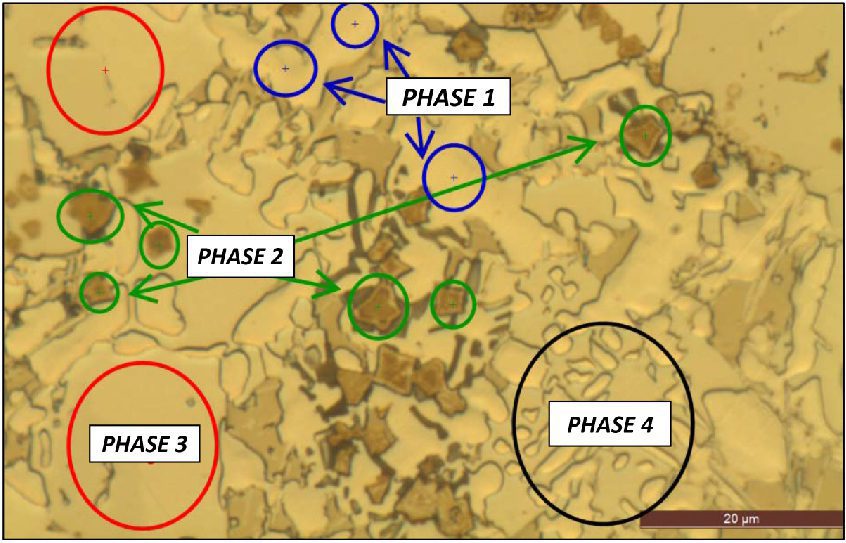
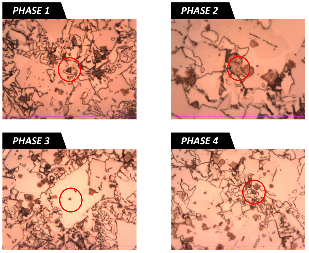
In this study, we use a metallurgical sample with multiple phases. The sample had been polished to a mirror-like surface finish before the indentation tests. Four phases have been identified in the sample, namely PHASE 1, PHASE 2, PHASE 3 and PHASE 4 as shown below.

The Advanced Stage Controller is an intuitive sample navigation tool which automatically adjusts the speed of sample movement under the optical microscope based on position of the mouse. The further the mouse is away from the center of field of view, the faster the stage moves toward the mouse’s direction. This provides a user-friendly method to navigate the entire sample surface and select the intended location for mechanical testing. The coordinates of the test locations are saved and numbered, along with their individual test setups, such as loads, loading/unloading rate, number of tests in a map, etc. Such a test procedure allows users to examine a large sample surface for specific areas of interest for indentation and perform all the indentation tests at different locations in one time, making it an ideal tool for mechanical testing of metallurgical samples with multiple phases.

In this study, we located the specific phases of the sample under the optical microscope integrated in the NANOVEA Mechanical Tester as numbered on FIGURE 1. The coordinates of the selected locations are saved, followed by automatic nanoindentation tests all at once under the test conditions summarized below

FIGURE 1: SELECTING NANOINDENTATION LOCATION ON THE SAMPLE SURFACE.
RESULTS: NANOINDENTATIONS ON DIFFERENT PHASES

The indentations at the different phases of the sample are displayed below. We demonstrate that the excellent position control of the sample stage in the NANOVEA Mechanical Tester allows users to precisely pinpoint the target location for mechanical properties testing.

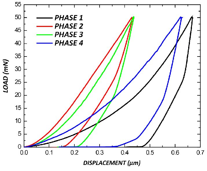
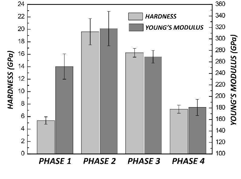
The representative load-displacement curves of the indentations are shown in FIGURE 2, and the corresponding hardness and Young’s Modulus calculated using Oliver and Pharr Methodiii are summarized and compared in FIGURE 3.


The
PHASES 1, 2, 3 and 4 possess an average hardness of ~5.4, 19.6, 16.2 and 7.2 GPa, respectively. The relatively small size for PHASES 2 contributes to its higher standard deviation of the hardness and Young’s Modulus values.

FIGURE 2: LOAD-DISPLACEMENT CURVES
OF THE NANOINDENTATIONS

FIGURE 3: HARDNESS & YOUNG’S MODULUS OF DIFFERENT PHASES

CONCLUSION

In this study, we showcased the NANOVEA Mechanical Tester performing nanoindentation measurements on multiple phases of a large metallurgical sample using the Advanced Stage Controller. The precise position control allows users to easily navigate a large sample surface and directly select the areas of interest for nanoindentation measurements.

The location coordinates of all the indentations are saved and then performed consecutively. Such a test procedure makes measurement of the local mechanical properties at small scales, e.g. the multi-phase metal sample in this study, substantially less time-consuming and more user friendly. The hard PHASES 2, 3 and 4 improve the mechanical properties of the sample, possessing an average hardness of ~19.6, 16.2 and 7.2 GPa, respectively, compared to ~5.4 GPa for PHASE 1.

The Nano, Micro or Macro modules of the instrument all include ISO and ASTM compliant indentation, scratch and wear tester modes, providing the widest and most user friendly range of testing available in a single system. NANOVEA’s unmatched range is an ideal solution for determining the full range of mechanical properties of thin or thick, soft or hard coatings, films and substrates, including hardness, Young’s modulus, fracture toughness, adhesion, wear resistance and many others.

i Oliver, W. C.; Pharr, G. M., Journal of Materials Research., Volume 19, Issue 1, Jan 2004, pp.3-20
ii Schuh, C.A., Materials Today, Volume 9, Issue 5, May 2006, pp. 32–40
iii Oliver, W. C.; Pharr, G. M., Journal of Materials Research, Volume 7, Issue 6, June 1992, pp.1564-1583

NOW, LET'S TALK ABOUT YOUR APPLICATION

Dynamic Mechanical Analysis (DMA) Frequency Sweep on Polymer


DMA FREQUENCY SWEEP

ON POLYMER USING NANOINDENTATION

Prepared by

Duanjie Li, PhD

INTRODUCTION

IMPORTANCE OF DYNAMIC MECHANICAL ANALYSIS FREQUENCY SWEEP TEST

The changing frequency of the stress often leads to variations in the complex modulus, which is a critical mechanical property of polymers. For example, tires are subjected to cyclical high deformations when vehicles are running on the road. The frequency of the pressure and deformation changes as the car accelerates to higher speeds. Such a change can result in variation in the viscoelastic properties of the tire, which are important factors in the car performance. A reliable and repeatable test of the viscoelastic behavior of polymers at different frequencies is in need. The Nano module of the NANOVEA Mechanical Tester generates sinusoidal load by a high precision piezo actuator and directly measures the evolution of force and displacement using ultrasensitive load cell and capacitor. The combination of easy setup and high accuracy makes it an ideal tool for Dynamic Mechanical Analysis frequency sweep.

Viscoelastic materials exhibit both viscous and elastic characteristics when undergoing deformation. Long molecular chains in polymer materials contribute to their unique viscoelastic properties, i.e. a combination of the characteristics of both elastic solids and Newtonian fluids. Stress, temperature, frequency and other factors all play roles in the viscoelastic properties. Dynamic Mechanical Analysis, also known as DMA, studies the viscoelastic behavior and complex modulus of the material by applying a sinusoidal stress and measuring the change of strain.

MEASUREMENT OBJECTIVE

In this application, we study viscoelastic properties of a polished tire sample at different DMA frequencies using the Most Powerful Mechanical Tester, NANOVEA PB1000, in Nanoindentation mode.

NANOVEA

PB1000

TEST CONDITIONS

FREQUENCIES (Hz):

0.1, 1.5, 10, 20

CREEP TIME AT EACH FREQ.

50 sec

OSCILLATION VOLTAGE

0.1 V

LOADING VOLTAGE

1 V

indenter type

Spherical

Diamond | 100 μm

RESULTS & DISCUSSION

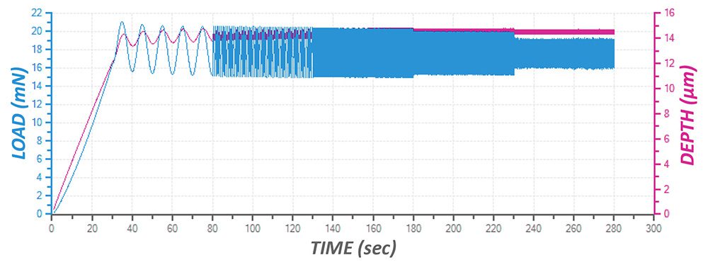
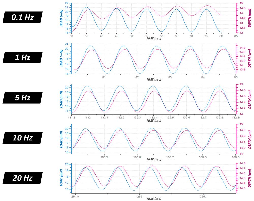
The Dynamic Mechanical Analysis frequency sweep at the maximum load allows a fast and simple measurement on the viscoelastic characteristics of the sample at different loading frequencies in one test. The phase shift and the amplitudes of the load and displacement waves at different frequencies can be used to calculate a variety of fundamental material viscoelastic properties, including Storage Modulus, Loss Modulus and Tan (δ) as summarized in the following graphs. 

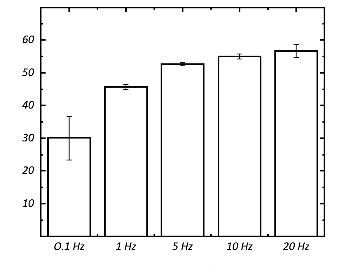
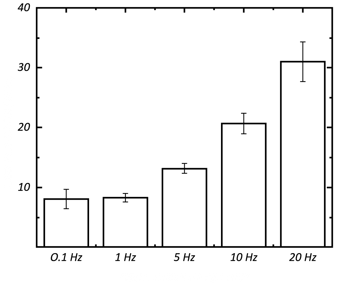
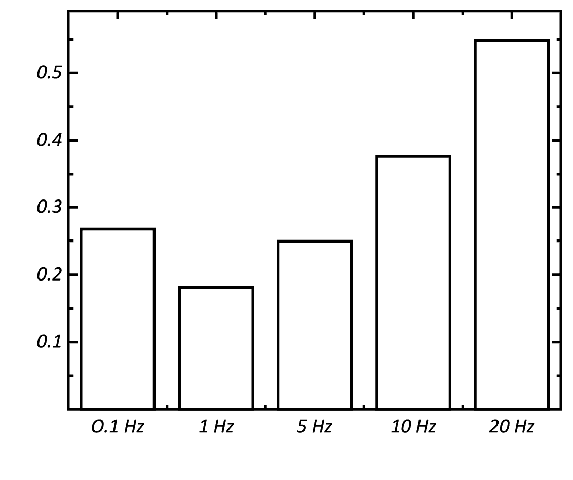
Frequencies of 1, 5, 10 and 20 Hz in this study, correspond to speeds of about 7, 33, 67 and 134 km per hour. As the test frequency increases from 0.1 to 20 Hz, it can be observed that both Storage Modulus and Loss Modulus progressively increase. Tan (δ) decreases from ~0.27 to 0.18 as the frequency increases from 0.1 to 1 Hz, and then it gradually increases to ~0.55 when the frequency of 20 Hz is reached. DMA frequency sweep allows measuring the trends of Storage Modulus, Loss Modulus and Tan (δ), which provide information on the movement of the monomers and cross-linking as well as the glass transition of polymers. By raising the temperature using a heating plate during the frequency sweep, a more complete picture of the nature of the molecular motion under different test conditions can be obtained.

EVOLUTION OF LOAD & DEPTH

OF THE FULL DMA FREQUENCY SWEEP

LOAD & DEPTH vs TIME AT DIFFERENT FREQUENCIES

STORAGE MODULUS

AT DIFFERENT FREQUENCIES

LOSS MODULUS

AT DIFFERENT FREQUENCIES

TAN (δ)

AT DIFFERENT FREQUENCIES

CONCLUSION

In this study, we showcased the capacity of the NANOVEA Mechanical Tester in performing the Dynamic Mechanical Analysis frequency sweep test on a tire sample. This test measures the viscoelastic properties of the tire at different frequencies of stress. The tire shows increased storage and loss modulus as the loading frequency increases from 0.1 to 20 Hz. It provides useful information on the viscoelastic behaviors of the tire running at different speeds, which is essential in improving the performance of tires for smoother and safer rides. The DMA frequency sweep test can be performed at various temperatures to mimic the realistic working environment of the tire under different weather.

In the Nano Module of the NANOVEA Mechanical Tester, the load application with the fast piezo is independent from the load measurement done by a separate high sensitivity strain gage. This gives a distinct advantage during Dynamic Mechanical Analysis since the phase between depth and load is measured directly from the data collected from the sensor. The calculation of phase is direct and does not need mathematical modeling that adds inaccuracy to the resulting loss and storage modulus. This is not the case for a coil-based system.

In conclusion, DMA measures loss and storage modulus, complex modulus and Tan (δ) as a function of contact depth, time and frequency. Optional heating stage allows determination of materials phase transition temperature during DMA. The NANOVEA Mechanical Testers provide unmatched multi-function Nano and Micro modules on a single platform. Both the Nano and Micro modules include scratch tester, hardness tester and wear tester modes, providing the widest and most user friendly range of testing available on a single module.

NOW, LET'S TALK ABOUT YOUR APPLICATION

Microparticles: Compression Strength and Micro Indentation

 

MICROPARTICLES

COMPRESSION STRENGTH & MICRO INDENTATION
BY TESTING SALTS​

Author:
Jorge Ramirez

Revised by:
Jocelyn Esparza

INTRODUCTION

Compression strength has become vital to quality control measurement in developing and improving new and existing microparticles and micro features (pillars and spheres) seen today. Microparticles have various shapes, sizes and can be developed from ceramics, glass, polymers, and metals. Uses include drug delivery, food flavor enhancement, concrete formulations among many others. Controlling the mechanical properties of microparticles or microfeatures are critical for their success and requires the ability to quantitatively characterize their mechanical integrity  

IMPORTANCE OF DEPTH VERSUS LOAD COMPRESSION STRENGTH

Standard compressive measurement instruments are not capable of low loads and fail to provide adequate depth data for microparticles. By using Nano or Microindentation, the compression strength of nano or microparticles (soft or hard) can be accurately and precisely measured.  

MEASUREMENT OBJECTIVE

In this application note we measure  the compression strength of salt with the NANOVEA Mechanical Tester in micro indentation mode.

NANOVEA

CB500

TEST CONDITIONS

maximum force

30 N

loading rate

60 N/min

unloading rate

60 N/min

indenter type

Flat Punch

Steel | 1mm Diameter

Load vs depth curves

Results & Discussion

Height, failure force and strength for Particle 1 and Particle 2

Particle failure was determined to be the point where the initial slope of the force vs. depth curve began to noticeably decrease.This behavior shows the material has reached a yield point and is no longer able to resist the compressive forces being applied. Once the yield point is surpassed, the indentation depth begins to exponentially increase for the duration of the loading period. These behaviors can be seen in Load vs Depth Curves for both samples.

CONCLUSION

In conclusion, we have shown how the NANOVEA Mechanical Tester in micro indentation mode is a great tool for compression strength testing of microparticles. Although the particles tested are made of the same material, it is suspected that the different failure points measured in this study were likely due to pre-existent micro cracks in the particles and varying particle sizes. It should be noted that for brittle materials, acoustic emission sensors are available to measure the beginning of crack propagation during a test.


The
NANOVEA Mechanical Tester offers depth displacement resolutions down to the sub nanometer level,
making it a great tool for the study of very fragile micro particles or features as well. For soft and fragile
materials, loads down to 0.1mN are possible with our nano indentation module

NOW, LET'S TALK ABOUT YOUR APPLICATION

Ceramics: Nanoindentation Fast Mapping for Grain Detection

INTRODUCTION


Nanoindentation has become a widely applied technique for measuring mechanical behaviors of materials at small scalesi ii. The high-resolution load-displacement curves from a nanoindentation measurement can provide a variety of physicomechanical properties, including hardness, Young’s modulus, creeping, fracture toughness and many others.


Importance of Fast Mapping Indentation


One significant bottleneck for further popularization of the nanoindentation technique is time consumption. A mechanical property mapping by conventional nanoindentation procedure can easily take hours which hinders the application of the technique in mass production industries, such as semiconductor, aerospace, MEMS, consumer products such as ceramic tiles and many others.

Fast mapping can prove to be essential in the ceramic tile manufacturing industry, Hardness and Young’s modulus mappings across a single ceramic tile can present a distribution of data that indicates how homogeneous the surface is. Softer regions on a tile can be outlined in this mapping and show locations more prone to failure from physical impacts that happen on a day to day basis in someone’s residence. Mappings can be made on different types of tiles for comparative studies and on a batch of similar tiles to measure tile consistency in a quality control processes. The combination of measurements setups can be extensive as well as accurate and efficient with the fast mapping method.


MEASUREMENT OBJECTIVE


In this study, the Nanovea Mechanical Tester, in FastMap mode is used to map the mechanical property of a floor tile at high speeds. We showcase the capacity of the Nanovea Mechanical Tester in performing two fast nanoindentation mappings with high precision and reproducibility.


Test Conditions


The Nanovea Mechanical Tester was used to perform a series of nanoindentations with the FastMap Mode on a floor tile using a Berkovich indenter. The test parameters are summarized below for the two indent matrices created.


Table 1:  Test parameter summary.


RESULTS & DISCUSSION 
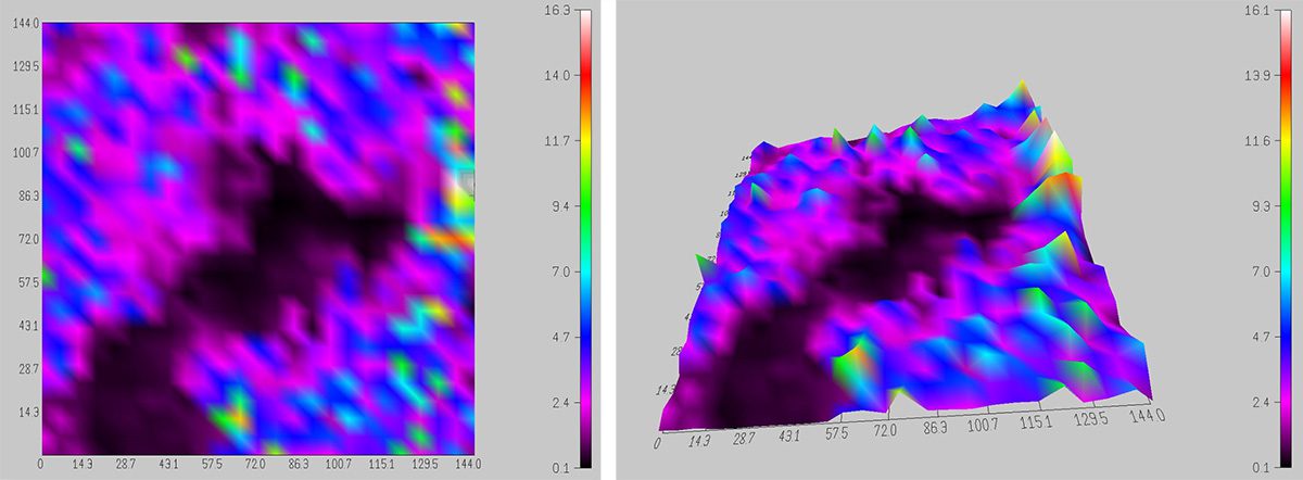
 

Figure 1:  2D and 3D view of 625-indent hardness mapping.
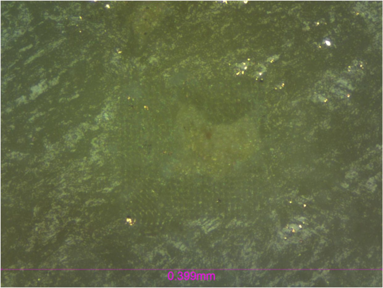


Figure 2:  Micrograph of 625-indent matrix showcasing grain.


A 625-indent matrix was conducted on a 0.20mm2 area with a large visible grain present. This grain (Figure 2) had an average hardness lower than the overall surface of the tile. The Nanovea Mechanical Software allows the user to see the hardness distribution map in 2D and 3D mode which are depicted in Figure 1. Using the high-precision position control of the sample stage, the software allows users to target areas such as these for in depth mechanical properties mapping.
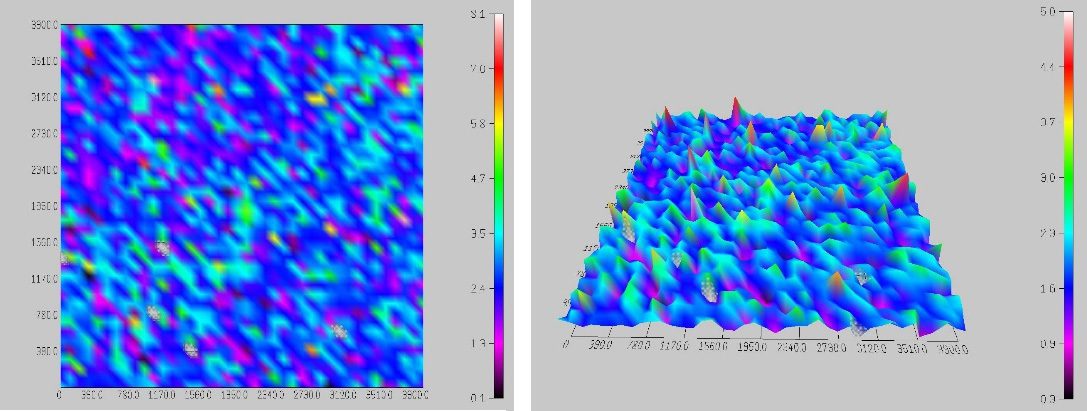
Figure 3:  2D and 3D view of 1600-indent hardness mapping.



Figure 4:  Micrograph of 1600-indent matrix.


A 1600-indent matrix was also created on the same tile to measure the homogeneity of the surface. Here again the user has the ability to see the hardness distribution in 3D or 2D mode (Figure 3) as well as the microscope image of the indented surface. Based on the hardness distribution presented, it can be concluded that the material is porous due to the even scattering of high and low hardness data points.

Compared to conventional nanoindentation procedures, FastMap mode in this study is substantially less time-consuming and more cost-effective. It enables speedy quantitative mapping of mechanical properties including Hardness and Young’s Modulus and provides a solution for grain detection and material consistency which is critical for quality control of a variety of materials in mass production.



CONCLUSION


In this study, we showcased the capacity of the Nanovea Mechanical Tester in performing speedy and precise nanoindentation mapping using FastMap mode. The mechanical property maps on the ceramic tile utilize the position control (with 0.2µm accuracy) of the stages and force module sensitivity to detect surface grains and measure homogeneity of a surface at high speed.

The test parameters used in this study were determined based on the size of the matrix and sample material. A variety of test parameters can be chosen to optimize the total indentation cycle time to 3 seconds per indent (or 30 seconds for every 10 indentations).

The Nano and Micro modules of the Nanovea Mechanical Tester all include ISO and ASTM compliant indentation, scratch and wear tester modes, providing the widest and most user-friendly range of testing available in a single system. Nanovea’s unmatched range is an ideal solution for determining the full range of mechanical properties of thin or thick, soft or hard coatings, films and substrates, including hardness, Young’s Modulus, fracture toughness, adhesion, wear resistance and many others.

In addition, optional 3D non-contact profiler and AFM Module are available for high resolution 3D imaging of indentation, scratch and wear track in addition to other surface measurements such as roughness.


Author: Duanjie Li, PhD        Revised by Pierre Leroux & Jocelyn Esparza

Improve Mining Procedures With Microindendation


MICROINDENTATION RESEARCH AND QUALITY CONTROL

Rock mechanics is the study of the mechanical behavior of rock masses and is applied in mining, drilling, reservoir production, and civil construction industries. Advanced instrumentation with precise measurement of mechanical properties allows for part and procedure improvement within these industries. Successful quality control procedures are ensured by understanding rock mechanics at the micro scale.

Microindentation is a crucial tool used for rock mechanics related studies. These techniques advance excavation techniques by providing further understanding of rock mass properties. Microindentation is used to improve drill heads which improve mining procedures. Microindentation has been used to study chalk and powder formation from minerals. Microindentation studies can include hardness, Young’s modulus, creep, stress-strain, fracture toughness, and compression with a single instrument.


MEASUREMENT OBJECTIVE

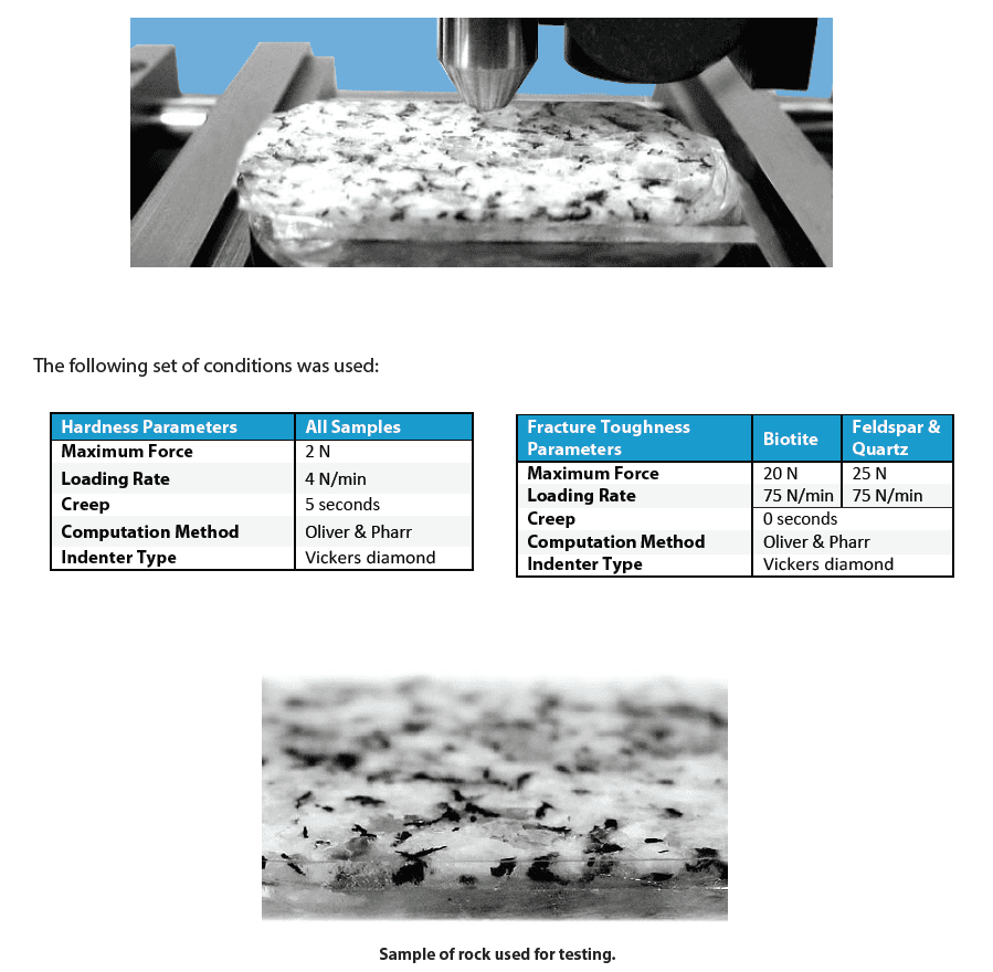
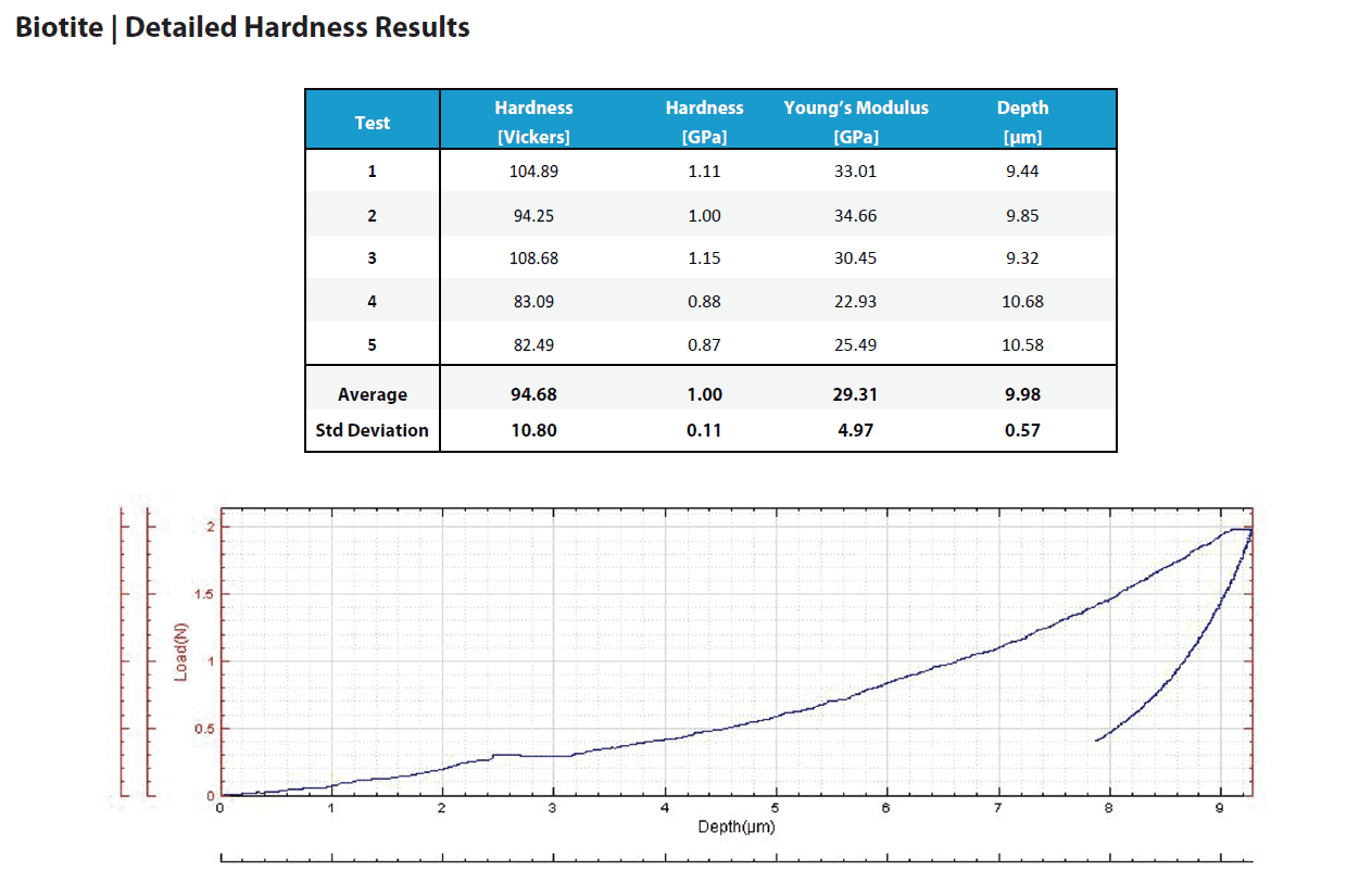
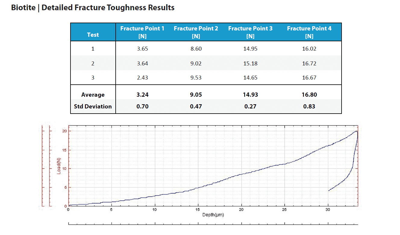
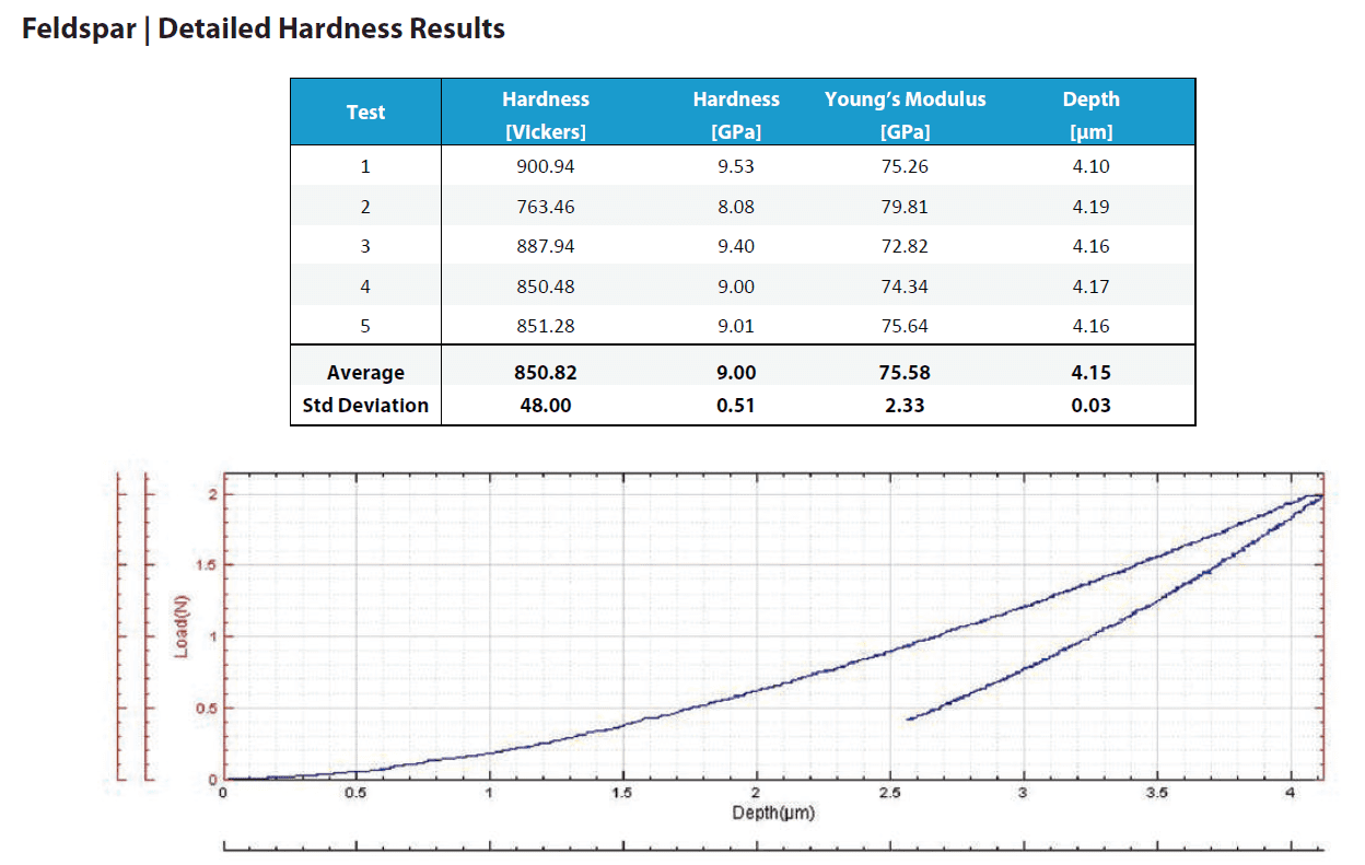
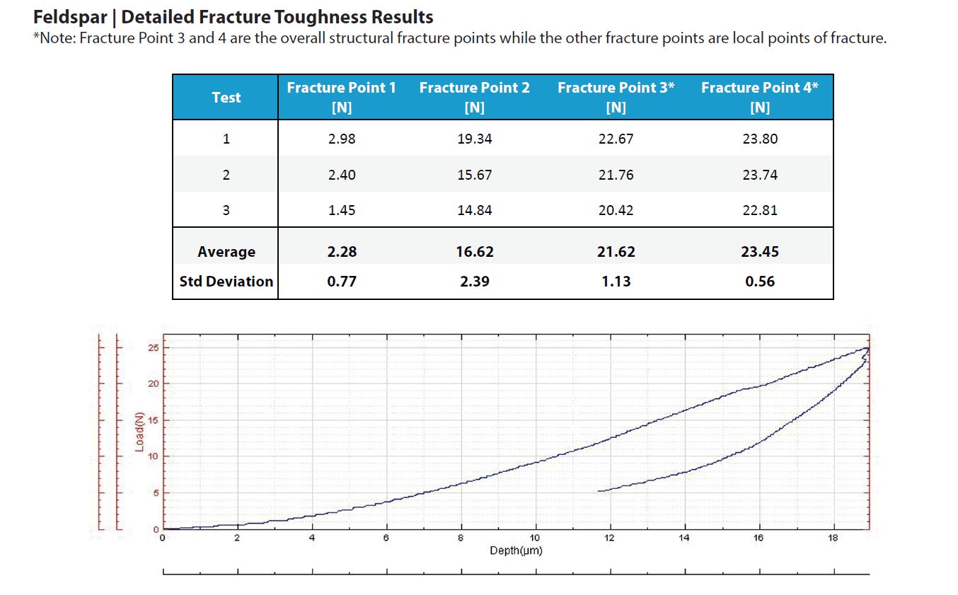
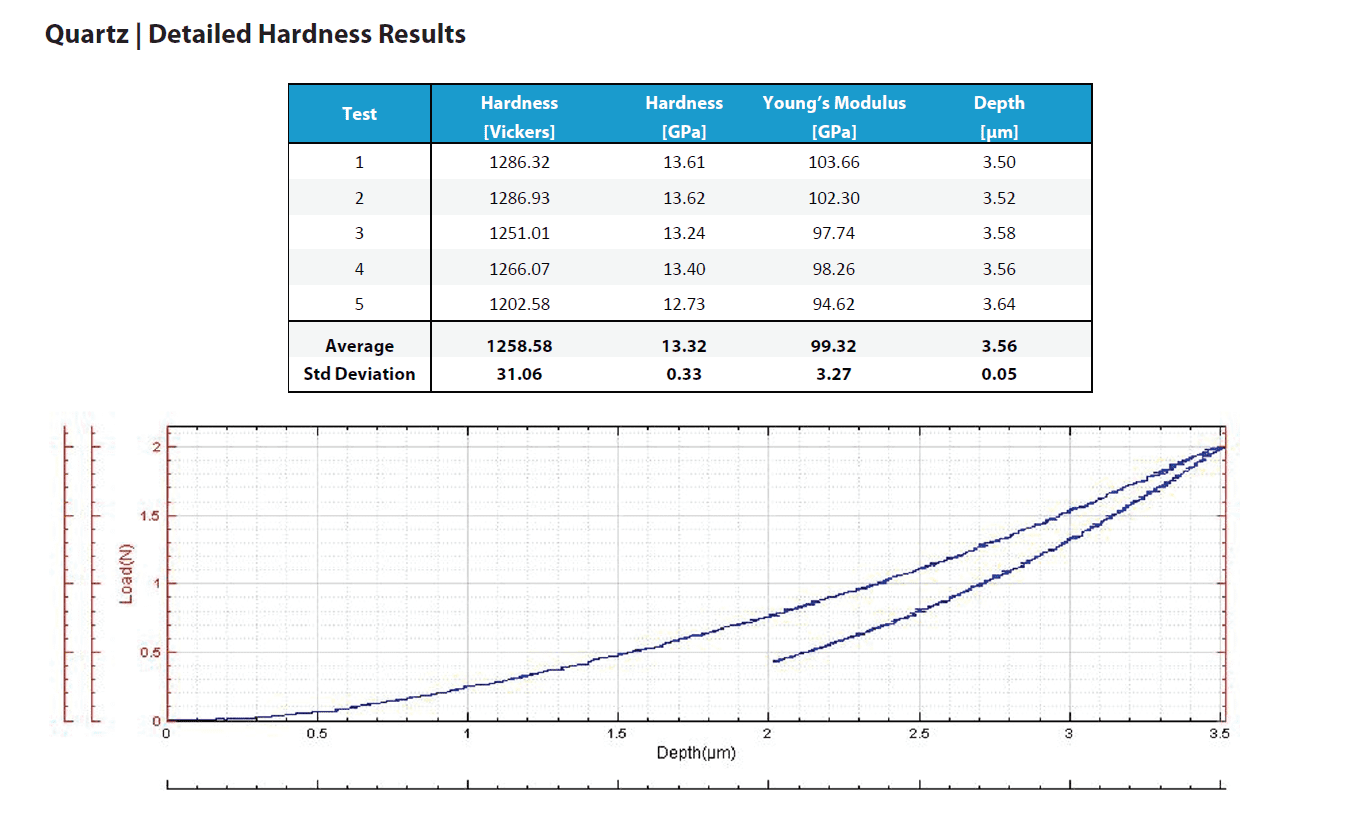
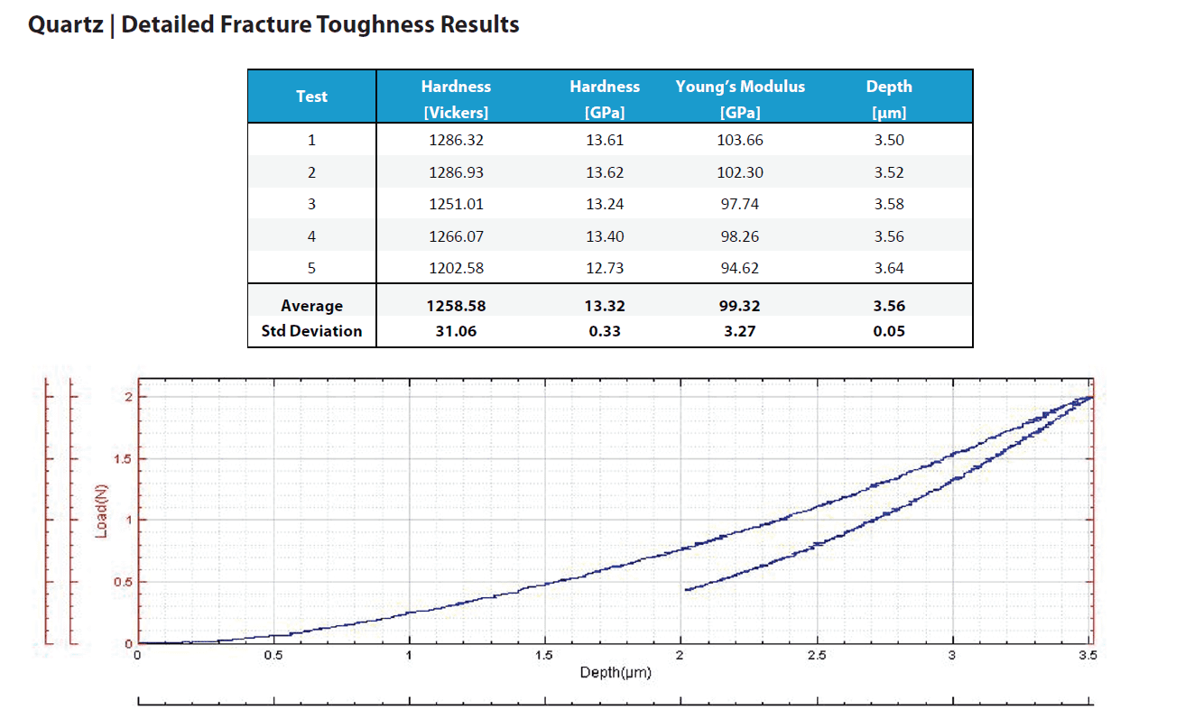
In this application the Nanovea mechanical tester measures the Vickers hardness (Hv), Young’s modulus, and fracture toughness of a mineral rock sample. The rock is made up of biotite, feldspar and quartz which form the standard granite composite. Each is tested separately.


RESULTS AND DISCUSSION

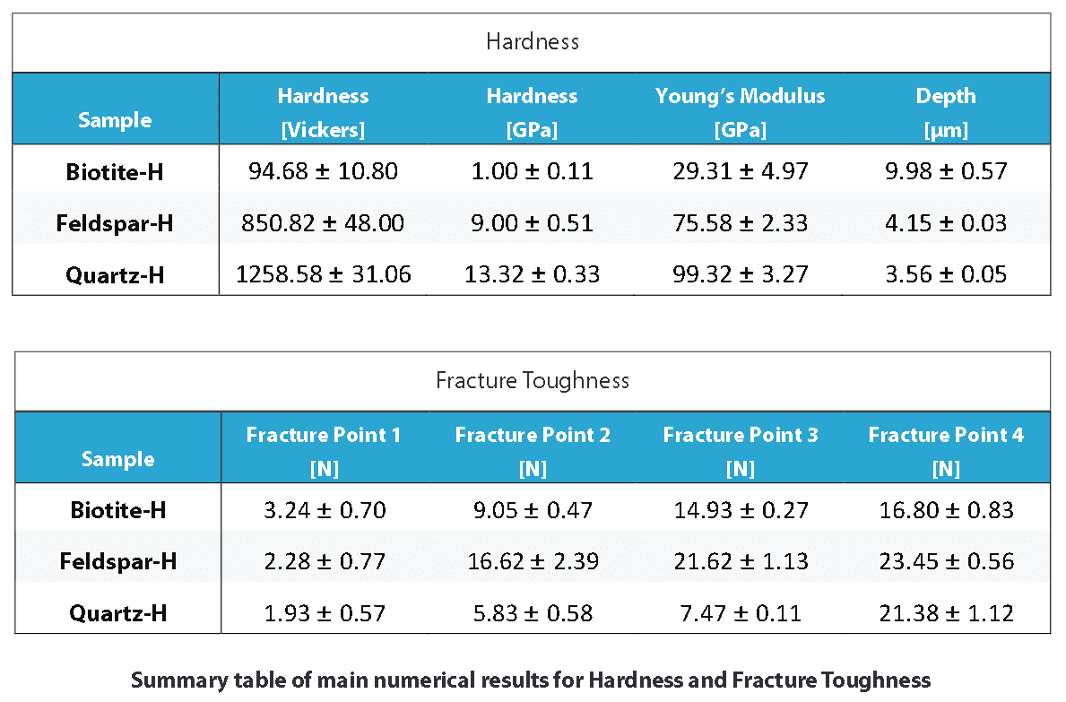
This section includes a summary table that compares the main numerical results for the different samples, followed by the full result listings, including each indentation performed, accompanied by micrographs of the indentation, when available. These full results present the measured values of Hardness and Young’s modulus as the penetration depth (Δd) with their averages and standard deviations. It should be considered that large variation in the results can occur in the case that the surface roughness is in the same size range as the indentation.


Summary table of main numerical results for Hardness and Fracture Toughness


CONCLUSION

The Nanovea mechanical tester demonstrates reproducibility and precise indentation results on the hard surface of mineral rock. Hardness and Young’s modulus of each material forming the granite was measured directly from depth versus load curves. The rough surface meant testing at higher loads that may have caused micro cracking. Micro cracking would explain some of the variations seen in measurements. Cracks were not perceivable through standard microscopy observation because of a rough sample surface. Therefore, it is not possible to calculate traditional fracture toughness numbers that requires cracks length measurements. Instead, we used the system to detect initiation of cracks through the dislocations in the depth versus load curves while increasing loads.

Fracture threshold loads were reported at loads where failures occurred. Unlike traditional fracture toughness tests that simply measure crack length, a load is obtained at which threshold fracture starts. Additionally, the controlled and closely monitored environment allows the measurement of hardness to use as a quantitative value for comparing a variety of samples.

NOW, LET'S TALK ABOUT YOUR APPLICATION

Biological Tissue Hardness Evaluation using Nanoindentation

Importance of Biological Tissue Nanoindentation

Traditional mechanical tests (hardness, adhesion, compression, puncture, yield strength, etc.) require greater precision and reliability in today’s quality control environments with a wide range of advanced materials from tissues to brittle materials. Traditional mechanical instrumentation fails to provide the sensitive load control and resolution required for advanced materials. The challenges associated with biomaterials require developing mechanical tests capable of accurate load control on extremely soft materials. These materials require very low sub mN testing loads with large depth range to ensure proper property measurement. In addition, many different mechanical test types can be performed on a single system allowing for greater functionality. This provides a range of important measurements on biomaterials including hardness, elastic modulus, loss and storage modulus, and creep in addition to scratch resistance and yield strength failure points.


Measurement Objective

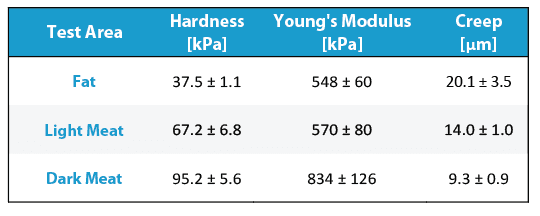
In this application Nanovea’s mechanical tester in nanoindentation mode is used to study the hardness and elastic modulus of 3 separate areas of a biomaterial substitute on fat, light meat, and dark meat regions of prosciutto.

Nanoindentation is based on instrumented indentation standards ASTM E2546 and ISO 14577. It uses established methods where an indenter tip of known geometry is driven into a specific site of the test material with a controlled increasing normal load. When reaching a pre-set maximum depth, normal load is reduced until complete relaxation occurs. Load is applied by a piezo actuator and measured in a controlled loop with a high sensitivity load cell. During experiments the indenter position relative to the sample surface is monitored with a high precision capacitive sensor. The resulting load and displacement curves provide data specific to the mechanical nature of the tested material. Established models calculate quantitative hardness and modulus values with the measured data. Nanoindentation is suited to low load and penetration depth measurements at nanometer scales.

Results and Discussion

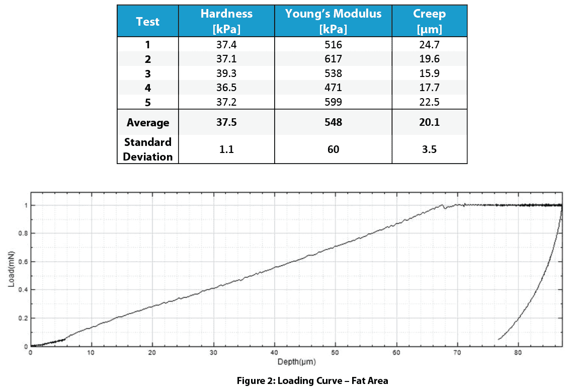
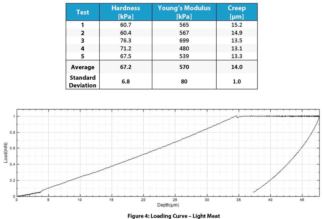
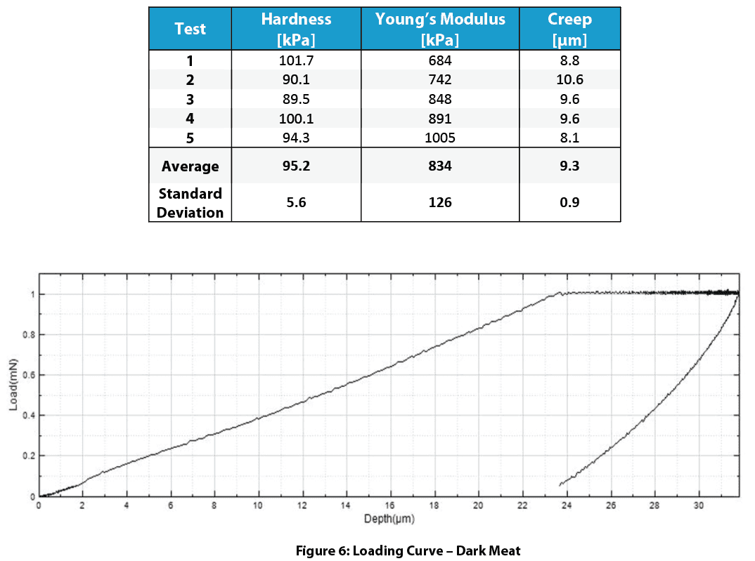
These tables below present measured values of hardness and Young’s modulus with averages and standard deviations. High surface roughness may cause large variations in the results due to small indentation size.

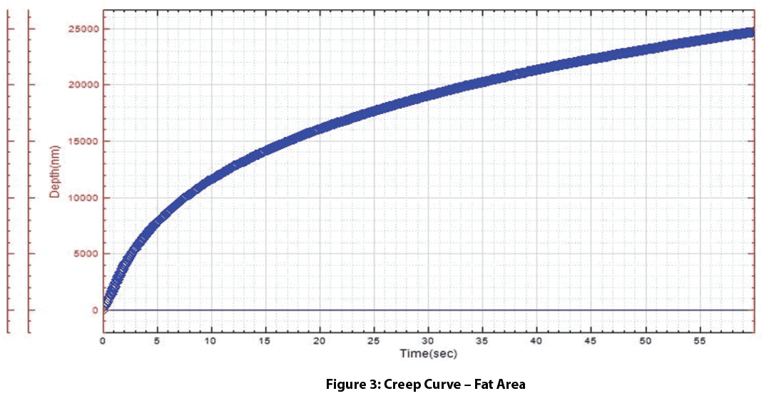
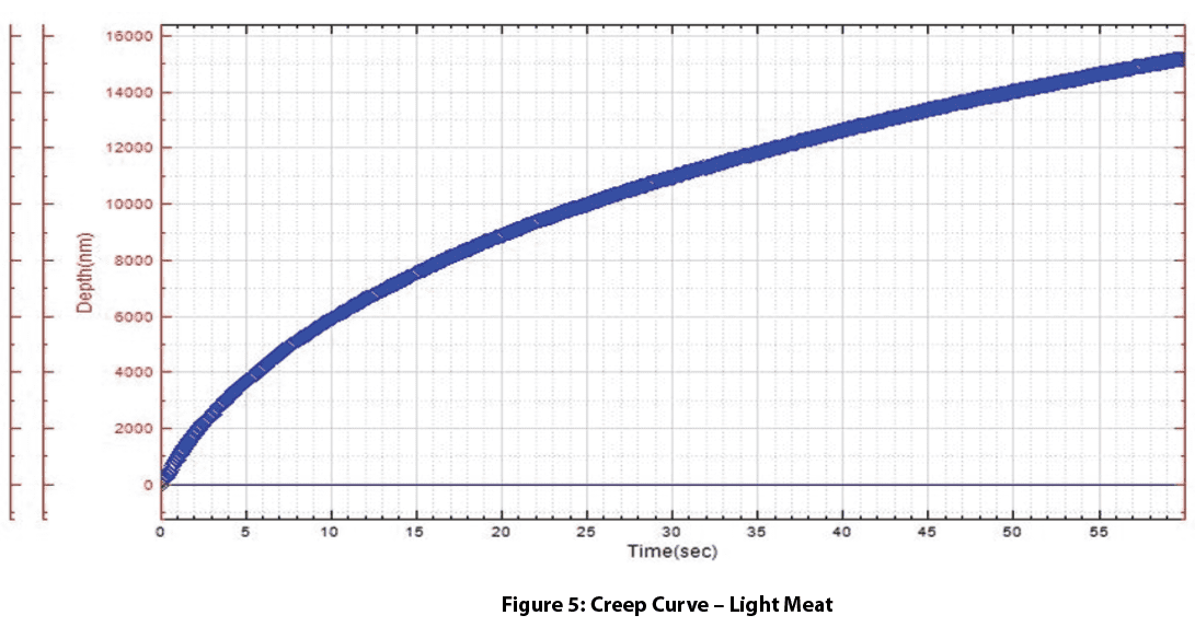
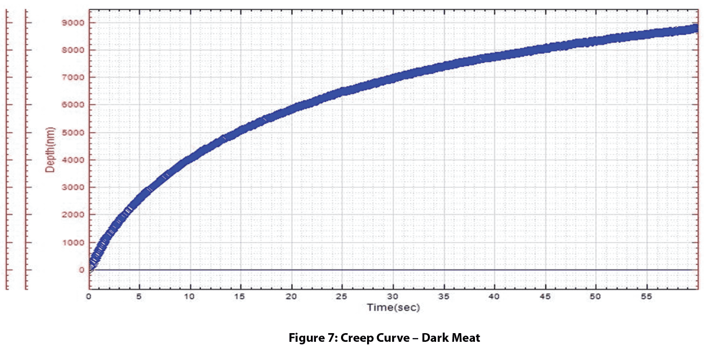
The fat area had about half the hardness of the meat areas. Meat treatment caused the darker meat area to be harder than the light meat area. Elastic modulus and hardness are in direct relation to mouth feel chewiness of the fat and meat areas. The fat and light meat area have creep continuing at a higher rate than the dark meat after 60 seconds.

Detailed Results – Fat

Detailed Results – Light Meat

Detailed Results – Dark Meat

Conclusion

In this application, Nanovea’s mechanical tester in nanoindentation mode reliably determined mechanical properties of the fat and meat areas while overcoming high sample surface roughness. This demonstrated the wide and unmatched capability of Nanovea’s mechanical tester. The system simultaneously provides precise mechanical property measurements on extremely hard materials and soft biological tissues.

The load cell in closed loop control with the piezo table ensures precise measurement of hard or soft gel materials from 1 to 5kPa. Using the same system, it is possible to test biomaterials at higher loads up to 400N. Multi-cycle loading can be used for fatigue testing and yield strength information in each zone can be obtained using a flat cylindrical diamond tip. In addition, with Dynamic Mechanical Analysis (DMA), the viscoelastic properties loss and storage moduli can be evaluated with high accuracy using the closed loop load control. Tests at various temperatures and under liquids are also available on the same system.

Nanovea’s mechanical tester continues to be the superior tool for biological and soft polymer/gel applications.

NOW, LET'S TALK ABOUT YOUR APPLICATION

Wear and Scratch Evaluation of Surface Treated Copper Wire


Importance of Wear and Scratch Evaluation of Copper Wire

Copper has a long history of use in electric wiring since the invention of the electromagnet and telegraph. Copper wires are applied in a wide range of electronic equipment such as panels, meters, computers, business machines, and appliances thanks to its corrosion resistance, solderability, and performance at elevated temperatures up to 150°C. Approximately half of all mined copper is used for manufacturing electrical wire and cable conductors.

Copper wire surface quality is critical to application service performance and lifetime. Micro defects in wires may lead to excessive wear, crack initiation and propagation, decreased conductivity, and inadequate solderability. Proper surface treatment of copper wires removes surface defects generated during wire drawing improving corrosion, scratch, and wear resistance. Many aerospace applications with copper wires require controlled behavior to prevent unexpected equipment failure. Quantifiable and reliable measurements are needed to properly evaluate the wear and scratch resistance of the copper wire surface.


Measurement Objective

In this application we simulate a controlled wear process of different copper wire surface treatments. Scratch testing measures the load required to cause failure on the treated surface layer. This study showcases the Nanovea Tribometer and Mechanical Tester as ideal tools for evaluation and quality control of electric wires.


Test Procedure and Procedures

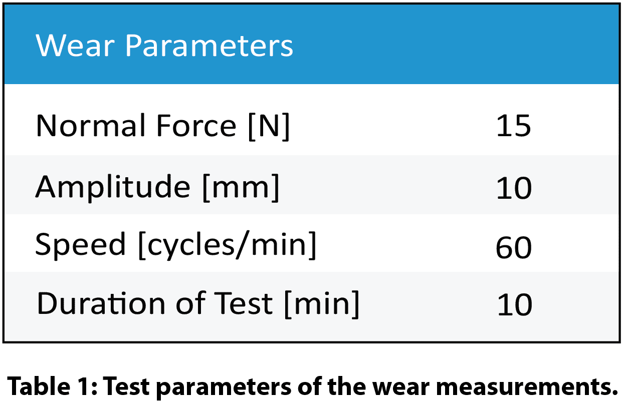
Coefficient of friction (COF) and wear resistance of two different surface treatments on copper wires (Wire A and Wire B) were evaluated by the Nanovea tribometer using a linear reciprocating wear module. An Al₂O₃ ball (6 mm diameter) is the counter material used in this application. The wear track was examined using Nanovea’s 3D non-contact profilometer. Test parameters are summarized in Table 1.

A smooth Al₂O₃ ball as a counter material was used as an example in this study. Any solid material with different shape and surface finish can be applied using a custom fixture to simulate the actual application situation.


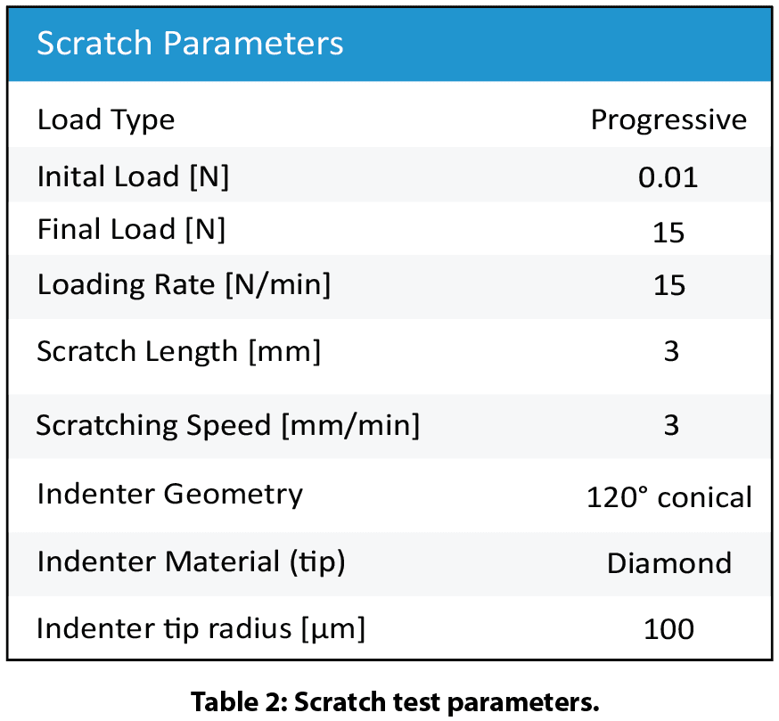
Nanovea’s mechanical tester equipped with a Rockwell C diamond stylus (100 μm radius) performed progressive load scratch tests on the coated wires using micro scratch mode. Scratch test parameters and tip geometry are shown in Table 2.


Results and Discussion

Wear of copper wire:

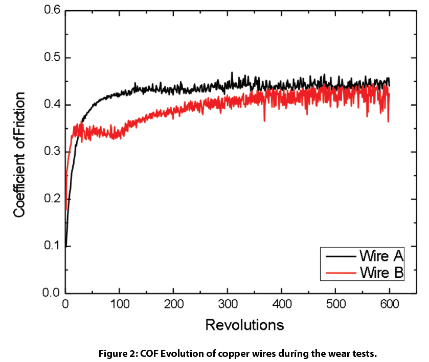
Figure 2 shows COF evolution of the copper wires during wear tests. Wire A shows a stable COF of ~0.4 throughout the wear test while wire B exhibits a COF of ~0.35 in the first 100 revolutions and progressively increases to ~0.4.


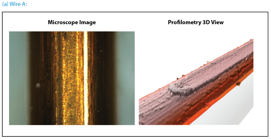
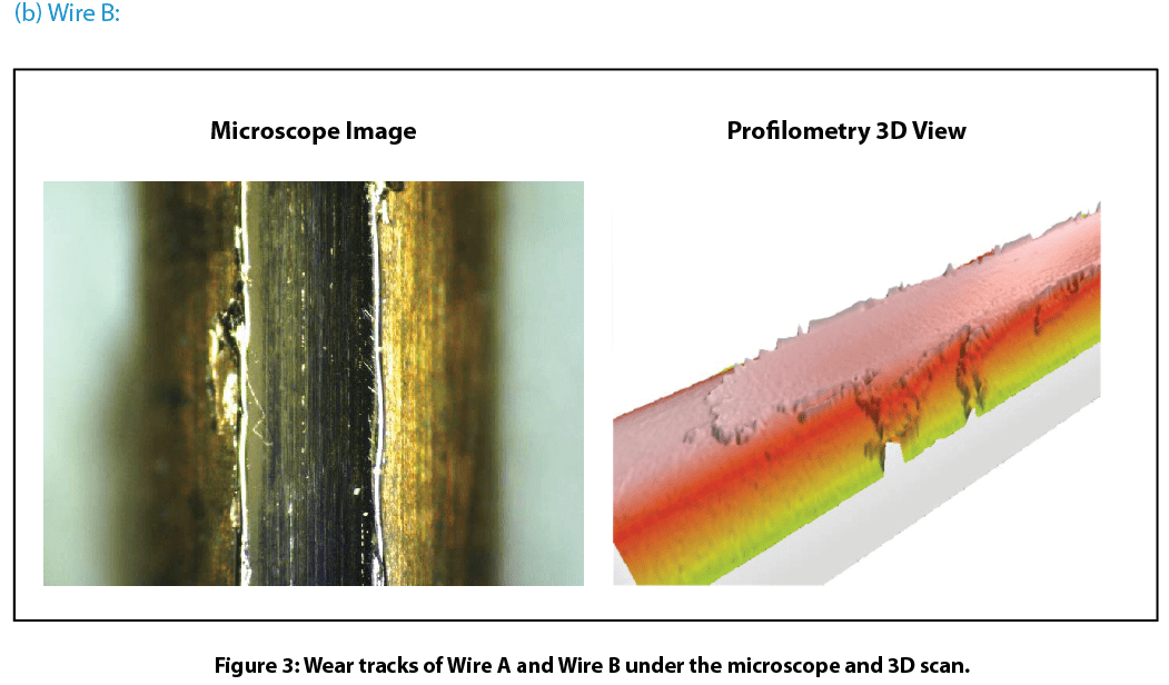
Figure 3 compares wear tracks of the copper wires after tests. Nanovea’s 3D non-contact profilometer offered superior analysis of the detailed morphology of wear tracks. It allows direct and accurate determination of the wear track volume by providing a fundamental understanding of the wear mechanism. Wire B’s surface has signi¬ficant wear track damage after a 600-revolution wear test. The profilometer 3D view shows the surface treated layer of Wire B removed completely which substantially accelerated the wear process. This left a flattened wear track on Wire B where copper substrate is exposed. This may result in significantly shortened lifespan of electrical equipment where Wire B is used. In comparison, Wire A exhibits relatively mild wear shown by a shallow wear track on the surface. The surface treated layer on Wire A did not remove like the layer on Wire B under the same conditions.

Scratch resistance of the copper wire surface:

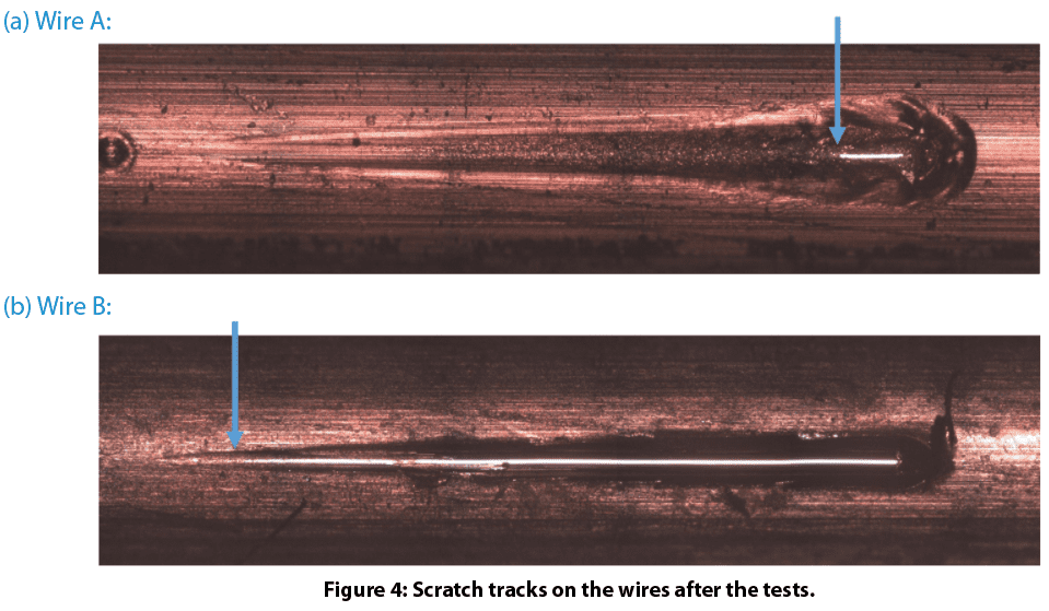
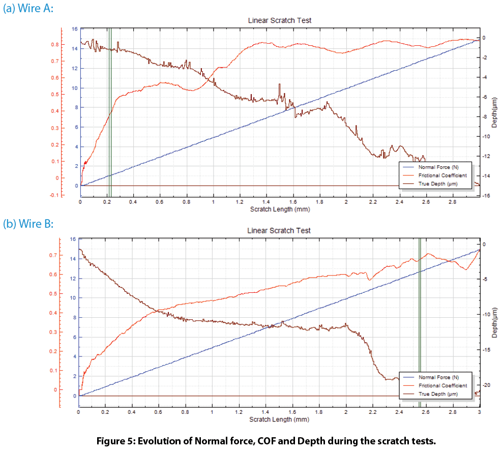
Figure 4 shows the scratch tracks on the wires after testing. The protective layer of Wire A exhibits very good scratch resistance. It delaminates at a load of ~12.6 N. In comparison, the protective layer of Wire B failed at a load of ~1.0 N. Such a significant difference in scratch resistance for these wires contributes to their wear performance, where Wire A possesses substantially enhanced wear resistance. The evolution of normal force, COF, and depth during the scratch tests shown in Fig. 5 provides more insight on coating failure during tests.

Conclusion

In this controlled study we showcased the Nanovea’s tribometer conducting quantitative evaluation of wear resistance for surface treated copper wires and Nanovea’s mechanical tester providing reliable assessment of copper wire scratch resistance. Wire surface treatment plays a critical role in the tribo-mechanical properties during their lifetime. Proper surface treatment on Wire A significantly enhanced wear and scratch resistance, critical in the performance and lifespan of electrical wires in rough environments.

Nanovea’s tribometer offers precise and repeatable wear and friction testing using ISO and ASTM compliant rotative and linear modes, with optional high temperature wear, lubrication, and tribo-corrosion modules available in one pre-integrated system. Nanovea’s unmatched range is an ideal solution for determining the full range of tribological properties of thin or thick, soft or hard coatings, films, and substrates.

NOW, LET'S TALK ABOUT YOUR APPLICATION

Yield and Tensile Strength of Steel and Aluminum

 

Importance of Yield Strength and Ultimate Tensile Strength Measurement using Indentation

Traditionally Yield Strength and Ultimate Tensile Strength have been tested using a large tensile testing machine requiring enormous strength to pull apart test specimens. It is costly and time-consuming to properly machine many test coupons for a material where each sample can only be tested once. Small defects in the sample create a noticeable variance in test results. Different configurations and alignments of the tensile testers in the market often result in substantial variations in testing mechanics and outcomes.

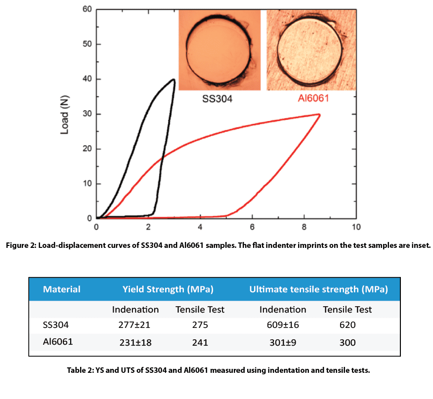
Nanovea’s innovative indentation method directly provides Yield Strength and Ultimate Tensile Strength values comparable to values measured by conventional tensile tests. This measurement opens a new realm of testing possibilities for all industries. The simple experimental setup significantly cuts sample preparation time and cost compared to the complex coupon shape required for tensile tests. Multiple measurements on a single sample are possible with a small indentation size. It prevents the influence of defects seen in tensile test coupons created during sample machining. YS and UTS measurements on small samples in localized area allow for mapping and local defect detection in pipelines or auto structures.


Measurement Objective

In this application, the Nanovea Mechanical Tester measures the Yield Strength and Ultimate Tensile Strength of stainless steel SS304 and aluminum Al6061 metal alloy samples. The samples were chosen for their commonly recognized Yield Strength and Ultimate Tensile Strength values showing the reliability of Nanovea’s indentation methods.

Test Procedure and Procedures

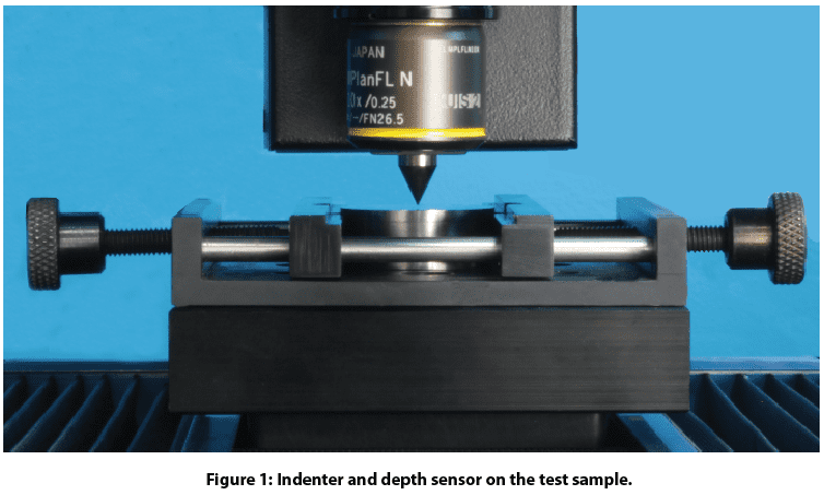
The Yield Strength and Ultimate Tensile Strength tests were performed on the Nanovea Mechanical Tester in the Microindentation mode. A cylindrical flat diamond tip of 200 μm diameter was used for this application. SS304 and Al6061 alloys were selected for their extensive industrial application and commonly recognized Yield Strength and Ultimate Tensile Strength values, in order to show the great potential and reliability of the indentation method. Samples were mechanically polished to a mirror-like finish before testing to avoid surface roughness or defect influence on test results. Test conditions are listed in Table 1. More than ten tests were performed on each sample to ensure the repeatability of the test values.

Results and Discussion

Load-displacement curves of the SS304 and Al6061 alloy samples are shown in Figure 3 with the flat indenter imprints on the test samples inset. Analysis of the “S” shaped loading curve using special algorithms developed by Nanovea calculates Yield Strength and Ultimate Tensile Strength . Values are automatically calculated by the software as summarized in Table 1. Yield Strength and Ultimate Tensile Strength values obtained by conventional tensile tests are listed for comparison.


Conclusion

In  this  study,  we  showcased  the  capacity  of  Nanovea  Mechanical  Tester  in  evaluating  Yield Strength & Ultimate Tensile Strength of stainless  steel and aluminum alloy sheet samples. The simple experimental setup significantly cuts the time and cost for  sample  preparation  required  for  tensile  tests.  The  small  indentation  size  makes  it  possible  to  perform  multiple measurements  on  one  single  sample.  This  method  allows  YS/UTS  measurements  on  small  samples  and localized areas, providing a solution for YS/UTS mapping and local defect detection of pipelines or auto structure.

The  Nano,  Micro  or  Macro  modules  of  the  Nanovea  Mechanical  Tester  all  include  ISO  and  ASTM  compliant              indentation,  scratch  and  wear  tester  modes,  providing  the  widest  and  most  user  friendly  range  of  testing  available in a single system. Nanovea’s unmatched range is an ideal solution for determining the full range of mechanical properties of thin or thick, soft or hard coatings, films and substrates, including hardness, Young’s modulus, fracture toughness, adhesion, wear resistance and many others.  In addition, optional 3D non-contact profiler and AFM Module are available for high resolution 3D imaging of indentation, scratch and wear track in addition to other surface measurements such as roughness.

NOW, LET'S TALK ABOUT YOUR APPLICATION

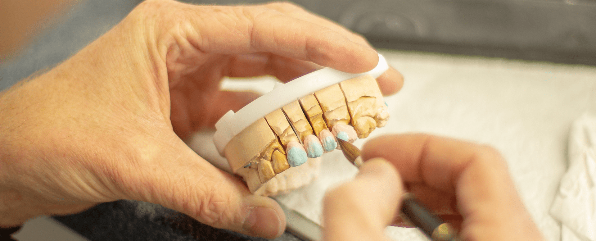
Tooth Hardness Evaluation using Nanoindentation

Importance of Nanoindentation for Bio Materials
 
With many traditional mechanical tests (Hardness, Adhesion, Compression, Puncture, Yield Strength, etc.), today’s quality control environments with advanced sensitive materials, from gels to brittle materials, now require greater precision and reliability control. Traditional mechanical instrumentation fails to provide the sensitive load control and resolution required; designed to be used for bulk materials. As the size of material being tested became of greater interest, the development of Nanoindentation provided a reliable method to obtain essential mechanical information on smaller surfaces such as the research being done with biomaterials. The challenges specifically associated with biomaterials have required the development of mechanical testing capable of accurate load control on extremely soft to brittle materials. Also, multiple instruments are needed to perform various mechanical tests which can now be performed on a single system. Nanoindentation provides a wide range of measurement with precise resolution at nano controlled loads for sensitive applications.


Measurement Objective

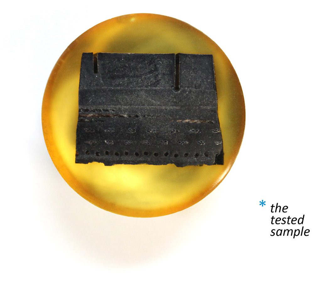
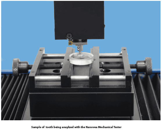
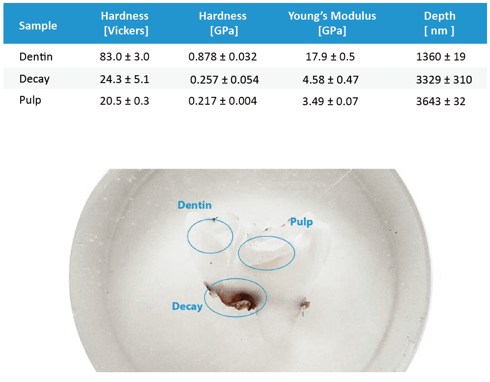
In this application, the Nanovea Mechanical Tester, in Nanoindentation mode, is used to study the hardness and elastic modulus of the dentin, decay, and pulp of a tooth. The most critical aspect with Nanoindentation testing is securing the sample, here we took a sliced tooth and epoxy mounted leaving all three areas of interest exposed for testing.


Results and Discussion

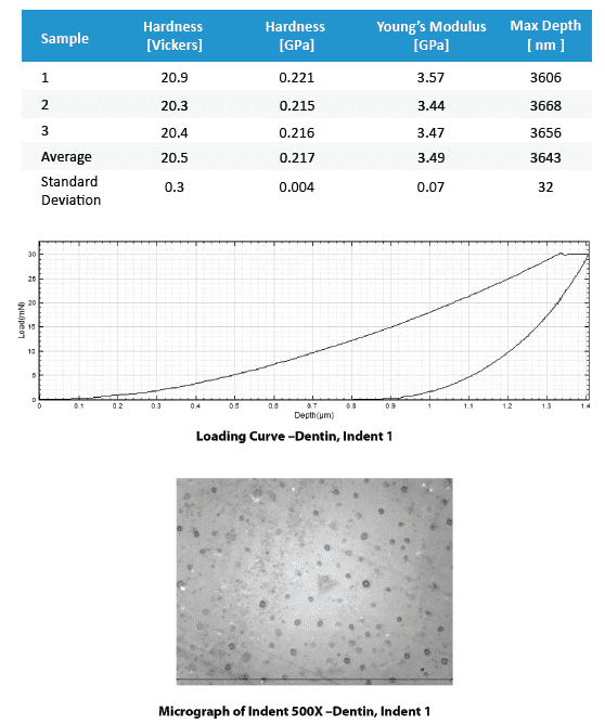
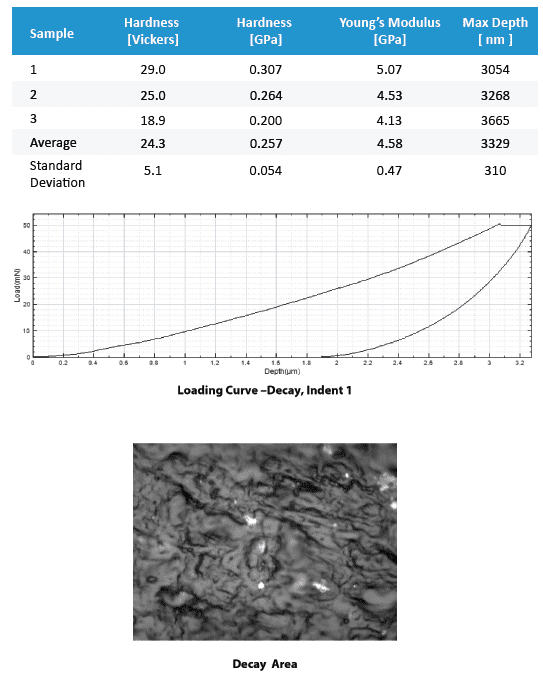
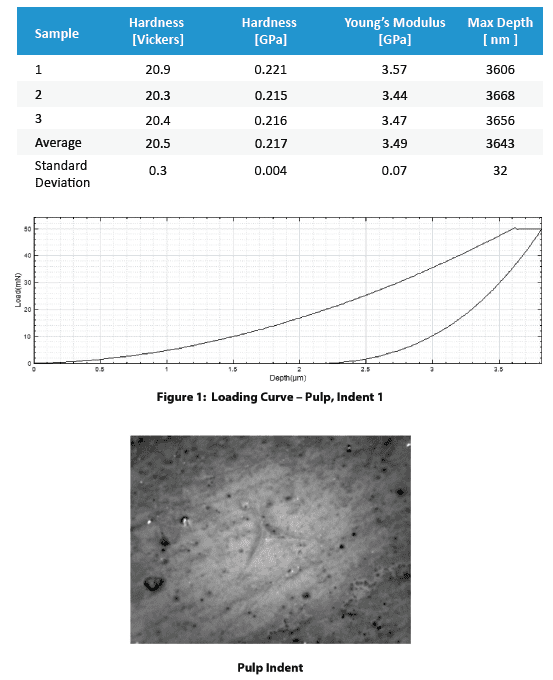
This section includes a summary table that compares the main numerical results for the different samples, followed by the full result listings, including each indentation performed, accompanied by micrographs of the indentation, when available. These full results present the measured values of Hardness and Young’s modulus as the penetration depth with their averages and standard deviations. It should be considered that large variation in the results can occur in the case that the surface roughness is in the same size range as the indentation.

Summary table of main numerical results:


Conclusion

In conclusion, we have shown how the Nanovea Mechanical Tester, in Nanoindentation mode, provides precise measurement of the mechanical properties of a tooth. The data can be used in the development of fillings that will better match the mechanical characteristics of a real tooth. The positioning capability of the Nanovea Mechanical Tester allows full mapping of the hardness of the teeth across the various zones.

Using the same system, it is possible to test teeth material fracture toughness at higher loads up to 200N. A multi-cycle loading test can be used on more porous materials to evaluate the remaining level of elasticity. Using a flat cylindrical diamond tip can give yield strength information in each zone. In addition, with DMA “Dynamic Mechanical Analysis”, the viscoelastic properties including loss and storage moduli can be evaluated.

The Nanovea nano module is ideal for these tests because it uses a unique feedback response to control precisely the load applied. Because of this, the nano module can also be used to do accurate nano scratch testing. The study of scratch and wear resistance of tooth material and filling materials adds to the overall usefulness of the Mechanical tester. Using a sharp 2-micron tip to quantitatively compare marring on filling materials will allow better prediction of the behavior in real applications. Multi-pass wear or direct rotative wear testing are also common tests providing important information on the long term viability.

NOW, LET'S TALK ABOUT YOUR APPLICATION