Category: Indentation | Hardness and Elastic
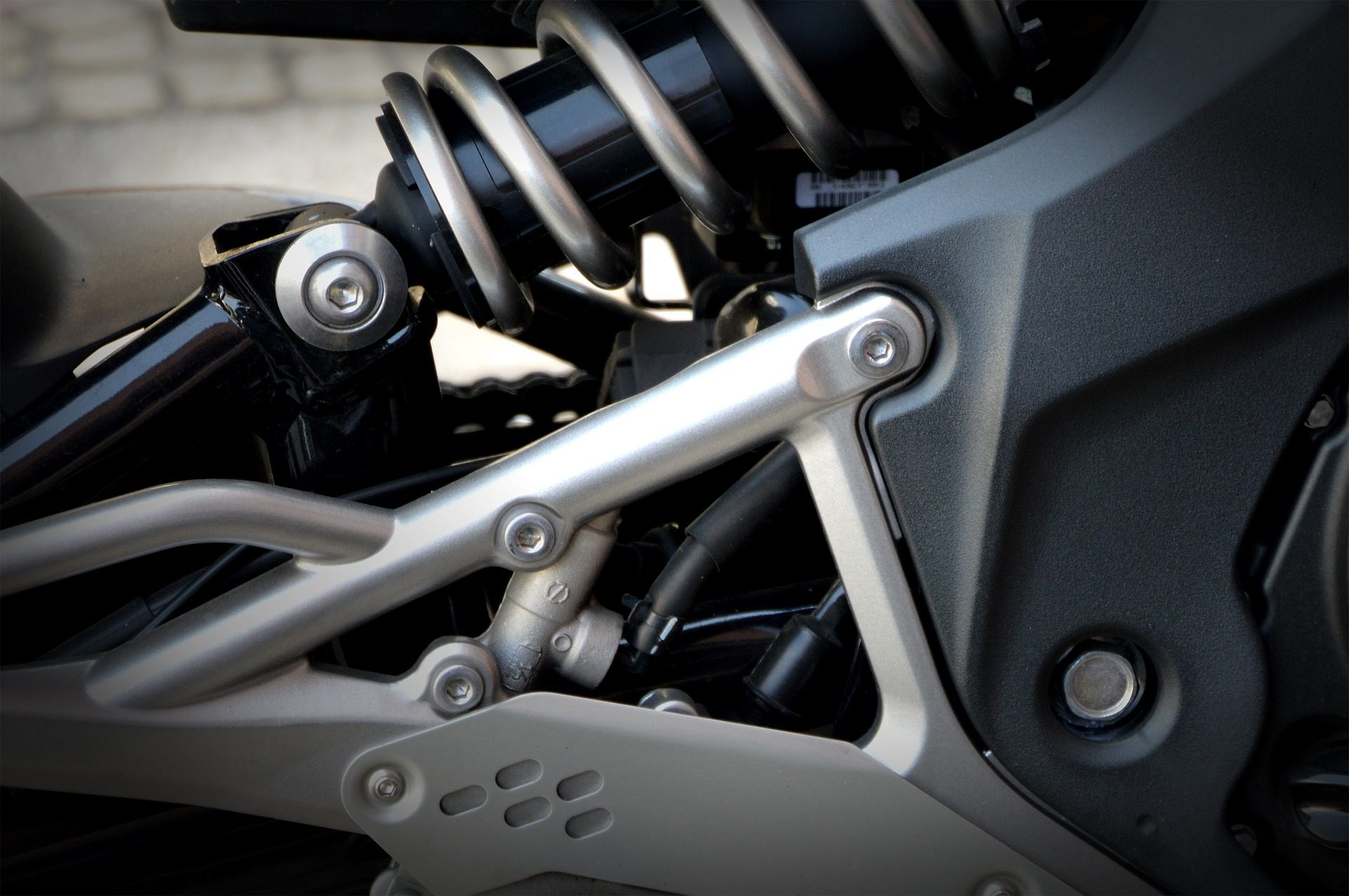
Nano Mechanical Characterization of Spring Constants
A spring’s ability to store mechanical energy has a long history of use. From bows for hunting to locks for doors, spring technology has been around for many centuries. Nowadays we rely on springs, be it from mattresses, pens, or automotive suspension, as they play a vital role in our daily lives. With such a wide variety of use and designs, the ability to quantify their mechanical properties is necessary.


Mechanical Broadview Map Selection Tool
We’ve all heard the term, time is money. Which is why many companies constantly seek methods of expediting and improving various processes, it saves time. When it comes to indentation testing, speed, efficiency and precision can be integrated into a quality control or R&D process when using one of our Nanovea Mechanical Testers. In this application note, we will be showcasing an easy way of saving time with our Nanovea Mechanical Tester and Broad View Map and Selection Tool software features.
Click to read the full application note!
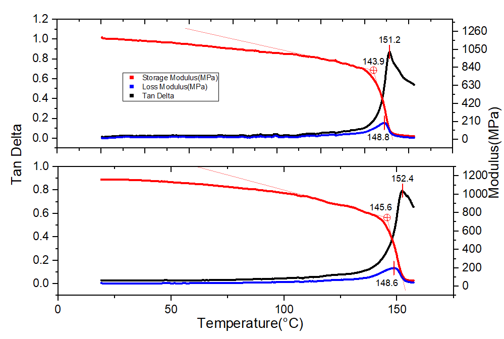
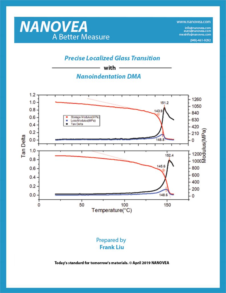
Precise Localized Glass Transition with Nanoindentation DMA


Imagine a scenario where a bulk sample is uniformly heated at a constant rate. As a bulk material heats up and approaches its melting point, it will start to lose its rigidity. If periodic indentations (hardness tests) are conducted at the same target force, the depth of each indent should be constantly increasing since the sample is becoming softer (see figure 1). This continues until the sample begins to melt. At this point, a large increase in the depth per indent will be observed. Using this concept, phase change in a material can be observed by using dynamic oscillations with a fixed force amplitude and measuring its displacement, i.e. Dynamic Mechanical Analysis (DMA).
Read about Precise Localized Glass Transition!

Compression on Soft, Flexible Materials
Importance of testing soft, flexible materials
An example of very soft and flexible samples is a microelectromechanical system. MEMS are used in everyday commercial products like printers, mobile phones, and cars [1]. Their uses also include special functions, such as biosensors [2] and energy harvesting [3]. For their applications, MEMS must be able to reversibly transition between their original configuration to a compressed configuration repeatedly [4]. To understand how the structures will react to mechanical forces, compression testing can be conducted. Compression testing can be utilized to test and tune various MEMS configurations as well as testing upper and lower force limits for these samples.
The Nanovea Mechanical Tester Nano Module’s ability to accurately collect data at very low loads and travel over 1mm of distance makes it ideal for testing the soft and exible samples. By having independent load and depth sensors, large indenter displacement does not affect the readings by the load sensor. The ability to carry out low-load testing over a range of more than 1mm of indenter travel makes our system unique compared to other nanoindentation systems. In comparison, a reasonable travel distance for a nanoscale indentation system is typically below 250μm.
Measurement Objective
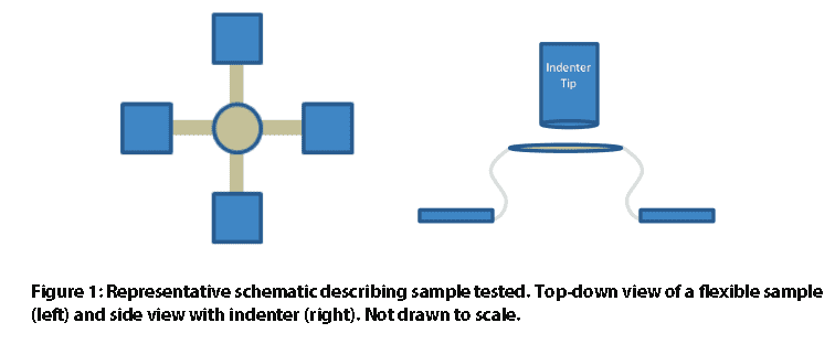
In this case study, Nanovea conducted compression testing on two uniquely di erent flexible, spring-like samples. We showcase our ability to conduct compression at very low loads and record large displacement while accurately obtaining data at low loads and how this can be applied to the MEMS industry. Due to privacy policies, the samples and their origin will not be revealed in this study
Measurement Parameters
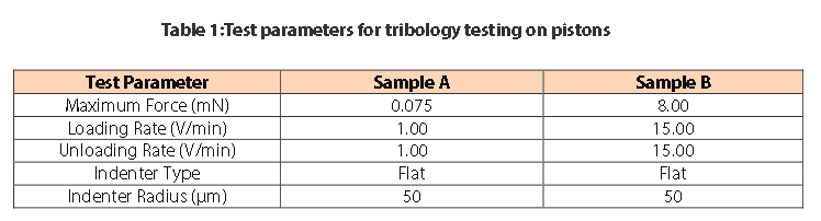
Note: The loading rate of 1 V/min is proportional to approximately 100μm of displacement when the indenter is in the air.
Results and Discussion
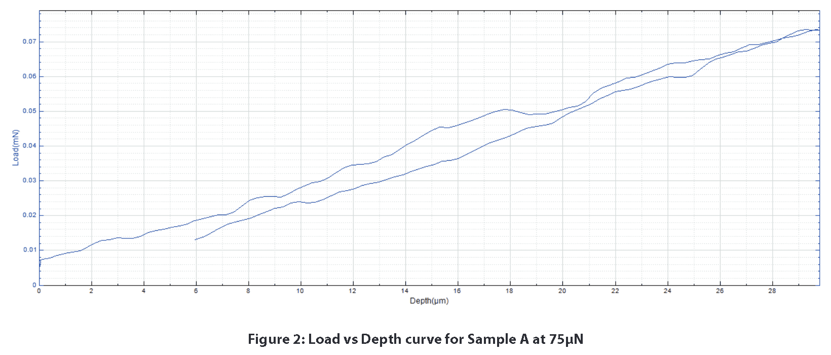
The sample’s response to mechanical forces can be seen in the load vs depth curves. Sample A only displays linear elastic deformation with the test parameters listed above. Figure 2 is a great example of the stability that can be achieved for a load vs. depth curve at 75μN. Due to the load and depth sensors stability, it would be easy to perceive any signi cant mechanical response from the sample.
Sample B displays a different mechanical response from Sample A. Past 750μm of depth, fracture-like behavior in the graph begins to appear. This is seen with the sharp drops in load at 850 and 975μm of depth. Despite traveling at a high loading rate for more than 1mm over a range of 8mN, our highly sensitive load and depth sensors allow the user to obtain the sleek load vs depth curves below.
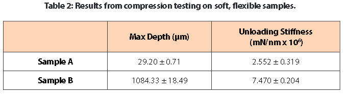
The stiffness was calculated from the unloading portion of the load vs depth curves. Stiffness reflects how much force is necessary to deform the sample. For this stiffness calculation, a pseudo Poisson’s ratio of 0.3 was used since the actual ratio of the material is not known. In this case, Sample B proved to be stiffer than Sample A.

Conclusion
Two diff erent flexible samples were tested under compression using the Nanovea Mechanical Tester’s Nano Module. The tests were conducted at very low loads (<80μN) and over a large depth range (>1mm). Nano-scaled compression testing with the Nano Module has shown the module’s ability to test very soft and flexible samples. Additional testing for this study could address how repeated cyclical loading a ects the elastic recovery aspect of the spring-like samples via the Nanovea Mechanical Tester’s multi-loading option.
For more information on this testing method, feel free to contact us at [email protected] and for additional application notes please browse our extensive Application Note digital library.
References
[1] “Introduction and Application Areas for MEMS.” EEHerald, 1 Mar. 2017, www.eeherald.com/section/design-guide/mems_application_introduction.html.
[2] Louizos, Louizos-Alexandros; Athanasopoulos, Panagiotis G.; Varty, Kevin (2012). “Microelectromechanical Systems and Nanotechnology. A Platform for the Next Stent Technological Era”. Vasc Endovascular Surg.46 (8): 605–609. doi:10.1177/1538574412462637. PMID 23047818.
[3] Hajati, Arman; Sang-Gook Kim (2011). “Ultra-wide bandwidth piezoelectric energy harvesting”. AppliedPhysics Letters. 99 (8): 083105. doi:10.1063/1.3629551.
[4] Fu, Haoran, et al. “Morphable 3D mesostructures and microelectronic devices by multistable bucklingmechanics.” Nature materials 17.3 (2018): 268.

Mechanical Properties of Silicon Carbide Wafer Coatings
Understanding the mechanical properties of silicon carbide wafer coatings is critical. The fabrication process for microelectronic devices can have over 300 different processing steps and can take anywhere from six to eight weeks. During this process, the wafer substrate must be able to withstand the extreme conditions of manufacturing, since a failure at any step would result in the loss of time and money. The testing of hardness, adhesion/scratch resistance and COF/wear rate of the wafer must meet certain requirements in order to survive the conditions imposed during the manufacturing and application process to insure a failure will not occur.
Controlled Humidity Nanoindentation of Polymer Films
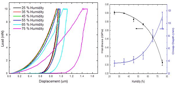
The mechanical properties of polymer is modified as the environmental humidity elevates. Transient moisture effects, a.k.a. mechano-sorptive effects arises as the polymer absorbs high moisture content and experiences accelerated creep behavior. The higher creep compliance is a result of complex combined effects such as increased molecular mobility, sorption-induced physical aging and sorption-induced stress gradients.
Therefore, a reliable and quantitative test (Humidity Nanoindentation)of the sorption-induced influence on the mechanical behavior of polymeric materials at different moisture level is in need. The Nano module of the Nanovea Mechanical Tester applies the load by a high-precision piezo and directly measures the evolution of force and displacement. Uniform humidity is created surrounding the indentation tip and the sample surface by an isolation enclosure, which ensures measurement accuracy and minimizes the influence of drift caused by humidity gradient.

Mechanical & Tribological Properties of Carbon Fiber
Combined with the wear test by Tribometer and surface analysis by Optical 3D Profilometer, we
showcase the versatility and accuracy of the Nanovea instruments in testing composite materials
with directional mechanical properties.
Biomechanical Hardness Evaluation of Tissue
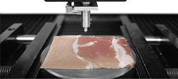
The ability to accurately measure mechanical properties in the fields of Life Science has recently become an important aspect of many current studies. In some cases, understanding the mechanical properties of soft biological surfaces have helped uncover the mechanical effects of diseases. Understanding mechanical properties provides a context for identifying the local mechanical behavior linked to specific changes. It is also critical in the development of artificial bio-materials. In this application, the Nanovea Mechanical Tester, in Nanoindentation mode, is used to study the biomechanical hardness and elastic modulus of 3 separate areas of prosciutto (fat, light meat and dark meat).

Tooth Hardness Evaluation Using Nanoindentation
In this application, the Nanovea Mechanical Tester, in Nanoindentation mode, is used to study the hardness and elastic modulus of the dentin, decay and pulp of a tooth. The most critical aspect with Nanoidentation testing is securing the sample, here we took a sliced tooth and epoxy mounted leaving all three area of interest exposed for testing.
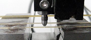
3 Point Bend Test Using Microindentation
In this application, the Nanovea Mechanical Tester, in Microindentation mode, is used to measure the flexural strength (using 3 Point Bend) of various sized rod samples (pasta) to show a range of data. 2 different diameters were chosen to demonstrate both elastic and brittle characteristics. Using a flat tip indenter to apply a point load, we determine stiffness (Young’s Modulus) and identify the critical loads at which the sample will fracture.


