Archivos mensuales: abril 2012
LA MEDICIÓN DE LA VERDAD. DESVENTAJAS DE LA INTERFEROMETRÍA
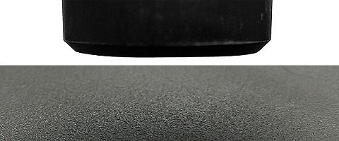
Algunas reflexiones sobre lo que hay que tener en cuenta al analizar las dos luces blancas. perfilómetro Las desventajas de la interferometría de luz blanca comienzan con el uso de software y ecuaciones matemáticas para detectar, a través del sistema de imágenes, el movimiento de las franjas a través de la pantalla a medida que la muestra o el cabezal de medición se mueven hacia arriba o hacia abajo en pasos específicos. Estas mediciones son tan buenas como lo que el software y las partes de imagen pueden hacer en términos de “detectar” el movimiento de estas franjas. Cuando se trata de superficies reflectantes y lisas, la precisión de los datos es superior. Por eso, esta técnica se ha desarrollado principalmente para aplicaciones de semiconductores, donde las superficies suelen ser reflectantes y los pasos, si los hay, son ángulos cercanos a los 90°.
Sin embargo, con una superficie rugosa y poco reflectante, la interpretación del software de la superficie real se aleja mucho de la realidad debido a los artefactos inherentes a la técnica de interferometría. Además, la interferometría también es extremadamente limitada en términos de medición de ángulos. Una vez más, el software puede ahora hacer milagros para completar superficies con información adicional, como la forma esperada de la superficie. La vista previa de los datos sin procesar es una forma de saber qué ha manipulado el software, pero incluso el software de análisis primario renderiza automáticamente una interpretación de cómo debe ser la superficie y completa automáticamente los puntos no medidos sin que el usuario lo sepa. Con un software inteligente, los artefactos pueden ser imposibles de distinguir de los datos reales, ya que la renderización de la imagen 3D se verá perfecta y, a menudo, los usuarios no saben cómo es realmente su superficie. Esto es especialmente cierto cuando se trata de superficies más complejas y difíciles.
Además, la velocidad se menciona como una diferencia importante entre las dos técnicas. Es cierto que la interferometría puede medir más rápidamente una imagen de campo de visión para evaluar la rugosidad y el escalón. Estas son ventajas claras cuando se trata de superficies semiconductoras lisas. Pero, de nuevo, si la superficie que se mide no es lisa, los datos pueden proporcionarse más rápidamente, pero estarán lejos de ser datos reales. Además, la unión de superficies funciona cuando, de nuevo, la superficie es lisa y reflectante y tiene marcadores de posición claros. La precisión del ensamblaje se reduce a medida que la superficie se vuelve más rugosa y con tipos de materiales más difíciles. Puede resultar difícil detectar artefactos y problemas con esto cuando la superficie es más rugosa que cuando se ve un escalón claro. Para obtener la mejor resolución lateral es necesario utilizar un objetivo de 100x, lo que limita el área de medición a aproximadamente 140 micrómetros x 110 micrómetros. El número de imágenes que se deben unir puede convertirse en un problema cuando se intenta obtener datos precisos sobre piezas más grandes (100 imágenes para 1 mm x 1 mm y 10 000 imágenes para 10 mm x 10 mm). La resolución lateral de la imagen depende del número de píxeles de la cámara que se utilice.
A diferencia de la técnica manipulativa de interferometría, la tecnología de cromatismo axial de luz blanca mide la altura directamente a partir de la detección de la longitud de onda que incide sobre la superficie de la muestra enfocada. Se trata de una medición directa sin manipulación matemática por parte del software. Esto proporciona una precisión inigualable en la superficie medida, ya que un punto de datos se mide con precisión sin interpretación del software o no se mide en absoluto. El software puede completar el punto no medido, pero el usuario es plenamente consciente de ello y puede estar seguro de que no hay otros artefactos ocultos. La técnica también puede medir casi cualquier superficie de material con ángulos mucho más altos, de hasta más de 80° en algunos casos. El cromatismo axial puede escanear una longitud de más de 30 cm en menos de 0,3 segundos. Ahora hay disponibles nuevos sistemas de adquisición que alcanzan los 31 000 puntos por segundo con un escaneo de 1 m/s. Los nuevos sensores lineales con cromatismo axial pueden medir hasta 324 000 puntos por segundo. Una imagen típica adquirida por un interferómetro tendría menos de 1 000 000 de puntos de datos por campo de visión. El escaneo con un sensor de línea con cromatismo axial tarda unos segundos, lo que significa que la velocidad real es muy similar a la de la interferometría, al tiempo que proporciona datos más precisos. Por lo tanto, la velocidad debe considerarse en función de la propia aplicación.
El crecimiento de la técnica de interferometría se debió principalmente a su éxito en industrias con mayor poder adquisitivo. Por lo tanto, el costo de la interferometría es generalmente el doble que el de los sistemas de cromatismo axial con resolución similar y mayor capacidad. Según nuestra experiencia, el 90% de las aplicaciones se beneficia más del uso de la técnica de cromatismo axial. Los clientes que han elegido la tecnología de cromatismo axial rara vez se han sentido decepcionados, mientras que la elección de la interferometría presenta muchos inconvenientes. Y el arrepentimiento es casi siempre el mismo: la desventaja de la interferometría es su amplia capacidad de medición y la fiabilidad de los datos, con un alto precio.
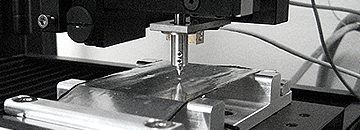
Resistencia a la perforación nanométrica mediante nanoindentación
En esta aplicación, el Nanovea Mechanical Tester, en Nanoindentación El modo se utiliza para estudiar la resistencia a la perforación de una muestra de lámina de aluminio utilizando un penetrador cilíndrico de punta plana. Se diseñó un soporte para muestras personalizado para fijar muestras de películas delgadas y láminas.
Resistencia a la perforación nanométrica mediante nanoindentación
Estos son algunos ejemplos de materiales que hemos probado este mes:
Mecánica:
• Nanoindentación de recubrimientos de sicn
• Nanoindentación tensión-deformación del polímero
• Límite elástico de nanoindentación de los MEMS
• Nanoarañazos en los recubrimientos de los catéteres
• Nanofricción de la película rtil
• Microarañazos en los recubrimientos de las tabletas.
• Microdesgaste del hilo de cobre micro.
Perfilometría 3D sin contacto:
• Topografía de una pieza automotriz fracturada
• Dimensión de las microcaracterísticas cerámicas
• Rugosidad de las muestras de PVC
• Rugosidad del molde de inyección de plástico
• Planitud de las muestras de vidrio
• Pérdida de volumen de las huellas de desgaste
Tribología:
• COF de diversas fórmulas de aceite
• COF del tubo médico de polímero
• Índice de desgaste de la junta de caucho
• Índice de desgaste de los recubrimientos de bobinas
• Índice de desgaste del acero recubierto de carbono


