Category: Application Notes
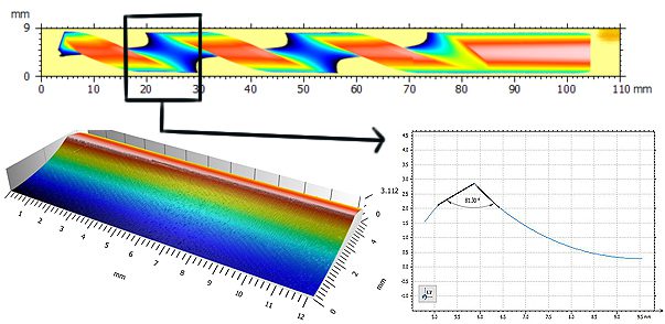
Cutting Tool Edge Measurement in Seconds
Irvine CA, July 27, 2016 – Conventional profilometry scans sample surfaces from a single, fixed direction. This is only appropriate for measuring sufficiently flat samples, as opposed to cylindrical shapes that require a precise 360° rotation. For an application such as characterizing the helical cutting edge of a tool, a conventional machine would need multiple scans from different angles of the entire part, as well as significant post scan data manipulation. This is often too time consuming for QC applications that only require measurements from very specific regions.
NANOVEA’S rotational stage solves this problem with simultaneous motion control of the lateral and rotational axes. This technique eliminates the time consuming need of measuring the entire part and continuous realignment. Instead, the full circumference of the entire cutting edge can be determined in seconds. All desired angles and features can be directly determined from the scan, with no need for the extensive stitching together of multiple files.
NANOVEA’s chromatic confocal technique offers far greater resolution, down to 2.7 nm, and accuracy than Focus Variation competitors. The raw surface height is measured directly from the detection of the wavelength focused on the surface, with none of the errors caused by Interferometry techniques, no field of view limitations, and no need for sample surface preparation. Materials with extremely high or low reflectivity can easily be measured and very high wall angles are accurately characterized without any issue.
Coupled with NANOVEA’s line sensor, a bar of data up to 4.78mm wide can be captured in a single pass, while moving linearly for up to 150mm in the scanning direction. Simultaneously, the rotational stage can revolve the sample at the desired speed. Put together, this system allows for the creation of a continuous 3D height map of the entire circumference of a cutting edge, with any pitch or radius, in a fraction of the time when compared to other technologies.
See App Note: Rotational Measurement Using 3D Profilometry
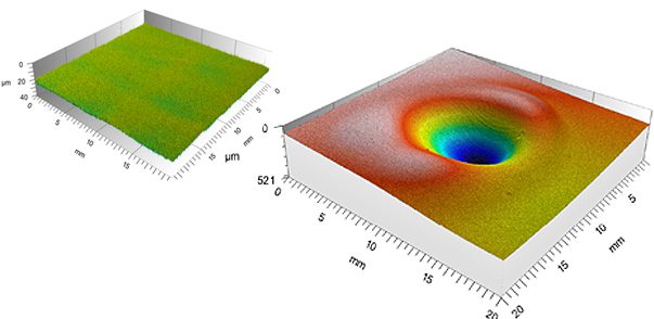
Polymer Morphology by Heat Deformation
Surface deformation of materials induced by environmental elements such as temperature, humidity and corrosion is vital to its service quality and functionality. Accurate 3D polymer morphology measurement allows quantifying the physical deformations of the surface form, roughness, volume/area, etc. Surfaces prone to deformation due to contact wear, high heat and others need regular inspection to ensure performance reliability.
Polymer Morphology by Heat Deformation Using 3D Profilometry
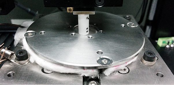
Teflon Mechanical Properties at High Temperature
At elevated temperatures, heat changes teflon mechanical properties such as the hardness and viscoelasticity, which may result in mechanical failures. A reliable measurement of the thermo-mechanical behavior of polymeric materials is in need to quantitatively evaluate the candidate materials for high temperature applications. The Nano module of the Nanovea Comprobador mecánico studies the Hardness, Young’s Modulus and Creep by applying the load with a high-precision piezo and measuring the evolution of force and displacement. An advanced oven creates a uniform temperature surrounding the indentation tip and the sample surface throughout the nanoindentation test so as to minimize the effect of thermal drift.
Teflon Mechanical Properties at High Temperature Using Nanoindentation
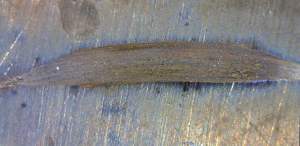
Desgaste recíproco por arco de alta temperatura
ASTM G133 3 is a widely used standard setup for testing the reciprocating sliding wear behaviors of materials. Due to the back and forth movement of the sample involved during the arc reciprocating wear testing, it is challenging to design an oven that fully enclose the sample and reaches a high and homogenous temperature. Our previous study has shown that the material tested using reciprocating and rotational setups can exhibit significantly different wear behaviors. Therefore, in order to study the reciprocating wear behaviors of materials at elevated temperatures, we developed the arc wear test setup. It rotates the sample stage for pin-on-disc test and continuously oscillates it clockwise and counterclockwise, creating a arc reciprocating sliding motion for the sample. The contact of the wear process can be totally enclosed in a large oven which ensures uniform and stable temperature up to 950oC surrounding the sample and the counter material.
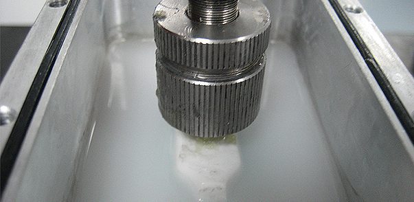
Brush Bristle Stiffness Performance Using Tribometer
Brushes are among the most basic and widely used tools in the world. They can be used to remove material (toothbrush, archaeological brush, bench grinder brush), apply material (paintbrush, makeup brush, gilding brush), comb filaments, or add a pattern. As a result of the mechanical and abrasive forces on them, brushes constantly have to be replaced after moderate use. For example toothbrush heads should be replaced every three to four months because of fraying as a result of repeated usage. Making the toothbrush fiber filaments too stiff risks wearing away the actual tooth instead of soft plaque. Making the toothbrush fibers too soft makes the brush lose its form faster. Understanding the changing bend of the brush, as well as the wear and overall change in shape in the filaments under different loading conditions is necessary to design brushes that better fulfill their application.
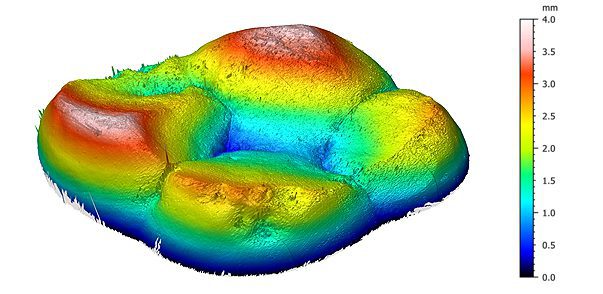
Dental Wear Surface Subtraction Using 3D Profilometry
Dental wear, the loss of tooth material due to reasons other than cavities and sudden dental trauma over the course of a lifetime, is a normal process in all adults. The topmost layer of a tooth is enamel, which is the hardest substance in the human body, and cannot be naturally restored. Enamel can wear away from tooth-to-tooth, tooth-to-foreign body, or tooth-to-dental crown wear, as well as a result of exposure to acidic environments. It is important to be able to precisely measure the wear rate, volume loss, and change in topography of a tooth or dental crown in order to be able to effectively slow down tooth wear. All these calculations can be made using a surface subtraction study.
Surface wear subtraction studies are critical in any application looking at the topographic change in a relatively small area in relation to the entire sample. Such studies can effectively quantify surface wear, corrosion, or the degree of similarity between two parts or molds. Being able to precisely measure the surface area and volume loss of an area of interest is vital in order to properly design wear or corrosion resistant coatings, films, and substrates
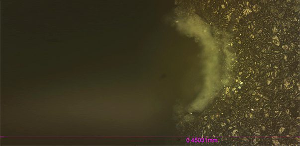
Edge Chipping Resistance Using Macroindentation
The resistance of the edges of brittle materials to chipping or flaking from concentrated loads is a critical property for dental restoration ceramics, resin composites, edge-mounted optical devices, ceramic tool bits, thin semiconductor chips, and many other materials. The edge chipping resistance test provides a method to quantify and measure the fracture resistance, toughness, and edge chip strength of these materials. This method uses a conical indenter to chip the rectangular edge of a brittle sample at set distances from the edge. Archeological evidence has revealed that this method is similar to the way early humans selected stones to make tools and weapons. Hundreds of thousands of years later, edge chipping tests remain a critical tool for applications where edge toughness is concerned.
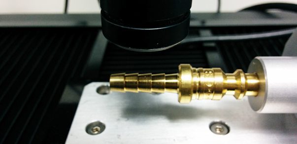
Rotational Measurement Using 3D Profilometry
Surface roughness and texture of the mechanical parts is vital to its end use. Conventional surface profilometry usually scan the sample surface from just one direction. A precise 360° rotational measurement of parts with a cylindrical shape is in need to measure detailed surface feature from different angles. Such 360° 3D inspection ensures the narrowest tolerances in quality control of manufacturing processes. Moreover, during the service time, wear creates dents, cracks, and surface roughening all over the cylindrical part surface. Surface inspection on one face of the sample may miss important information hidden on the backside.
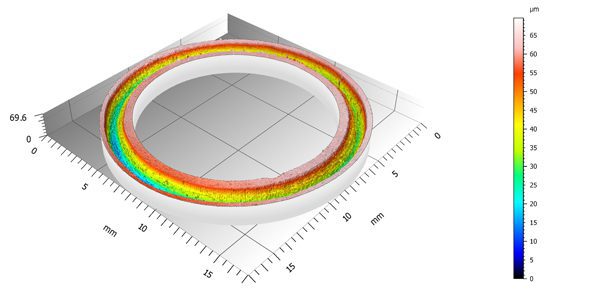
3D Wear Track Scan In Situ on Tribometer
Conventional pin-on-disc or reciprocating tribómetro records the COF during the wear test. The wear rate is measured after the wear test by moving the sample to a profilometer and scanning the cross section profiles of the wear track. Such a method may introduce errors when the sample possesses an inhomogeneous wear track. Moreover, samples like multilayer coatings possess different wear resistance at different layers of the coating. A more reliable and repeatable technique for wear evaluation is in need – Nanovea developed a tribometer equipped with a 3D non-contact profilometer that performs a 3D scan of the complete wear track on the sample stage of the tribometer. It monitors the evolution of the 3D wear track morphology, allowing users to accurately calculate the wear rate and determine the failure mode at different stages using one test sample.
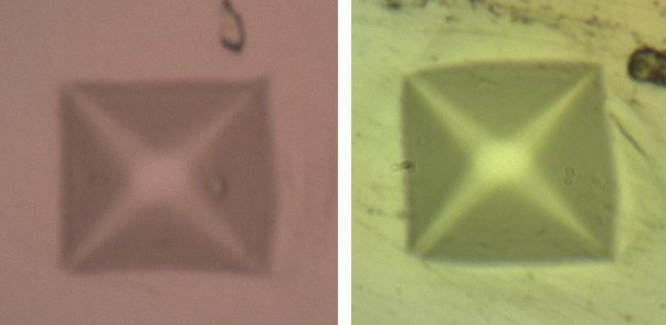
Low Load Vickers Hardness Measurement
During Vickers Hardness inevitable user errors are introduced during the measurement of the imprint under the microscope. Especially at low loads, small measurement errors of the indent size will produce large hardness deviations. In comparison, nanoindentation testing evaluates the mechanical properties of a material by driving the indenter tip into the test material and precisely recording the evolution of load and displacement of the tip. It avoids user errors in imprint size measurement.


